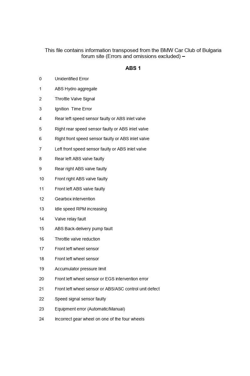
This file contains information transposed from the BMW Car Club of Bulgaria forum site (Errors and omissions excluded)
ABS 1
0 Unidentified Error
1 ABS Hydro aggregate
2 Throttle Valve Signal
3 Ignition Time Error
4 Rear left speed sensor faulty or ABS inlet valve
5 Right rear speed sensor faulty or ABS inlet valve
6 Right front speed sensor faulty or ABS inlet valve
7 Left front speed sensor faulty or ABS inlet valve
8 Rear left ABS valve faulty
9 Rear right ABS valve faulty
10 Front right ABS valve faulty
11 Front left ABS valve faulty
12 Gearbox intervention
13 Idle speed RPM increasing
14 Valve relay fault
15 ABS Back-delivery pump fault
16 Throttle valve reduction
17 Front left wheel sensor
18 Front left wheel sensor
19 Accumulator pressure limit
20 Front left wheel sensor or EGS intervention error
21 Front left wheel sensor or ABS/ASC control unit defect
22 Speed signal sensor faulty
23 Equipment error (Automatic/Manual)
24 Incorrect gear wheel on one of the four wheels
25 Line interruption – brake light switch
27 Idle speed feed back signal
30 Left rear wheel speed sensor cable
31 Right rear wheel speed sensor cable
32 Right front wheel speed sensor cable
33 Left front (E38/E39) or Right (E46) wheel speed sensor cable
34 Wheel sensor, front right or ASC switch over valve
35 Brake fluid level signal error
36 Front right wheel sensor or ignition signal error
37 Front right wheel sensor or ABS/ASC Control unit internal error
38 Gas valve adjustment error
39 Servo motor electrical error
40 Gas valve potentiometer error
41 Steering angle error
47 Fault, outlet valve, rear left
48 Fault, outlet valve, rear right
49 Wheel sensor, rear left or outlet valve front right
50 Wheel sensor, rear left or outlet valve front left
51 Fault, inlet valve, rear left
52 Wheel sensor rear left or inlet valve rear right
53 Wheel sensor rear left or inlet valve front right
54 Fault, inlet valve, front left
55 Fault, ASC shutoff valve
56 CAN Error (short circuit)
57 Throttle valve signal from the DME faulty
58 CAN Error (Open circuit to DME)
59 Fault, ASC shutoff valve
60 Signal, terminal 30 faulty
61 Central blocking
62 Max. ABD adjustment time
63 Processor fault in the control unit
64 Continuous control due to undefined signal interference
65 Wheel sensor rear right or bad feedback signal
66 Wheel sensor rear right or wheel speed sensor power supply
67 CAN Error
68 Wheel sensor rear right
69 Wheel sensor rear right
75 ASC indicator lamp
81 Inlet valve front left
82 Inlet valve front right
83 Inlet valve rear left
84 Inlet valve rear right
85 Outlet valve front left
86 Outlet valve front right
87 Outlet valve rear left
88 Outlet valve rear right
89 Power supply too low
90 Time limitation: passive switching
91 CAN Error
92 Pressure sensor (pre charging pump)
94 RPM sensor (Test)
95 Activation
96 Actuator test
97 ASC intake valve / Steering angle sensor
98 Separate valve
99 Electromagnetic switch over valve
100 Electromagnetic switch over valve
103 Brake light switch
104 Steering angle sensor
105 Brake light switch
106 Lateral acceleration sensor
107 RPM sensor (Gradient)
113 ABS/ASC feed back pump
115 ABS/ASC control unit internal error
118 Electromagnetic or mechanical influence on the wheel speed signals
120 Power supply voltage too high (>18V)
129 ABS/ASC Main relay circuit faulty
130 Power supply fault at the magnetic valves
131 Wrong current at magnetic valves
133 Power supply > too high
145 CAN chip in the ABS/ASC control unit
146 CAN Error
147 CAN Error – engine intervention
148 CAN Error – engine speed (RPM)
149 CAN Error – DME/DDE connection
150 CAN Error – EGS
151 Coding Error
152 DSC button
161 RPM sensor
162 RPM Signal
163 Lateral acceleration sensor
164 Lateral acceleration sensor
165 Pressure sensor 1
166 Pressure sensor 2
167 Pressure sensors
168 Pressure sensors power supply
177 Pre charge pump
178 Pre charge pump
180 Steering angle sensor (signal 1)
181 Steering angle sensor (identification)
182 Steering angle sensor (CAN)
183 Steering angle sensor (internal)
184 Steering angle sensor (offset)
ABS 2
0 Unidentified error – erase the error memory
2 EML interface fault – Check the connecting lines from Pins 6, 8 & 14 of the EML. If
the fault cannot be located, reset the error memory and run an
EGS Diagnostic check.
3 DME interface fault – Check control line Pin Check the size of tyres on all rims,
check wheel bearing clearance, pulse wheels, rotational speed
sensor (visual check for damage and dirt) 39 to the DME
4 Sensor fault rear left – Check the size of tyres on all rims, check wheel bearing
clearance, pulse wheels, rotational speed sensor (visual check
for damage and dirt)
5 Sensor fault rear right -Check the size of tyres on all rims, check wheel bearing
clearance, pulse wheels, rotational speed sensor (visual check
for damage and dirt)
6 Sensor fault front right -Check the size of tyres on all rims, check wheel bearing
clearance, pulse wheels, rotational speed sensor (visual check
for damage and dirt)
7 Sensor fault front left – Check the size of tyres on all rims, check wheel bearing
clearance, pulse wheels, rotational speed sensor (visual check
for damage and dirt)
8 ABS valve fault rear left – Check the plug and socket connection on the ABS hydraulic
aggregates for correct seating and corrosion. Check the wire
from Pin 2 of the ABS/ASC unit to Pin 5 of the ABS hydraulic
aggregate. If no fault is found, erase the stored fault codes
and re-diagnose. If fault reoccurs replace the control unit.
9 ABS valve fault rear right – Check the plug and socket connection on the ABS hydraulic
aggregates for correct seating and corrosion. Check the wire
from Pin 36 of the ABS/ASC unit to Pin 7 of the ABS hydraulic
aggregate. If no fault is found, erase the stored fault codes
and re-diagnose. If fault reoccurs replace the control unit.
10 ABS valve fault front right – Check the plug and socket connection on the ABS hydraulic
aggregates for correct seating and corrosion. Check the wire
from Pin 22 of the ABS/ASC unit to Pin 3 of the ABS hydraulic
aggregate. If no fault is found, erase the stored fault codes
and re-diagnose. If fault reoccurs replace the control unit.
11 ABS valve fault front left – Check the plug and socket connection on the ABS hydraulic
aggregates for correct seating and corrosion. Check the wire
from Pin 19 of the ABS/ASC unit to Pin 1 of the ABS hydraulic
aggregate. If no fault is found, erase the stored fault codes
and re-diagnose. If fault reoccurs replace the control unit.
12 Plunger valve fault rear left – Check supply voltage on the magnetic valve is 12v. Check
magnetic valve for visible damage and corrosion, if damaged
replace the magnetic valve.
13 Plunger valve fault – Check supply voltage on the magnetic valve is 12v. Check
magnetic valve for visible damage and corrosion, if damaged
replace the magnetic valve.
14 ABS valve relay fault – Reset the fault code and test drive the vehicle before re-
diagnosing. If fault code resets check the valve relay for
correct seating and contacts for corrosion. Check relay
operation by switching ignition on and off to ensure relay pulls
in and check supply voltage at valve relay.
15 Rear feed pump fault – Check engine relay for correct seating and contacts for
corrosion. Check ABS hydraulic aggregates earth connection
and earth connection and function of pump motor.
16 ASC+T storage load valve fault – Check function of magnetic valve plunger on hydraulic
aggregate.
17 Wheel sensor front/Inlet valve front left – Check connection between valve and master
relay and that master relay and valve are functioning properly.
18 Wheel sensor outlet/valve front left – Check connection between valve and master relay
and that master relay and valve are functioning properly.
20 Wheel sensor/inlet valve front right – Check connection between valve and master relay
and that master relay and valve are functioning properly.
24 Wheel sensor/outlet valve front right – Check connection between valve and master relay
and that master relay and valve are functioning properly.
33 Wheel sensor/Inlet valve rear left – Check connection between valve and master relay
and that master relay and valve are functioning properly.
34 Wheel sensor/outlet valve rear left – Check connection between valve and master relay
and that master relay and valve are functioning properly.
36 Inlet valve rear right
37 Front right wheel speed sensor
40 Rear output valve function
49 Power supply to magnetic valves
50 Throttle valve mechanical defect
56 ASC separate valve function faulty
65 ASC computer faulty
66 DME RPM signal faulty
68 Control unit defect – Replace ABS control unit
72 Internal fault – Replace ABS control unit
81 Rotational speed sensor front left – Check connection between rotational speed sensor
and control unit for short circuits or a broken connection
82 Rotational speed sensor front right – Check connection between rotational speed sensor
and control unit for short circuits or a broken connection
84 Rotational speed sensor rear left – Check connection between rotational speed sensor
and control unit for short circuits or a broken connection
88 Rotational speed sensor rear right – Check connection between rotational speed sensor
and control unit for short circuits or a broken connection
97 Rotational speed signal front left – Check plug and socket connections of rotational
speed sensor. Check air-gap between rotational speed sensor
and pulse wheel and reduce if necessary. Pulse wheel may
have incorrect number of teeth or rotational speed sensor
possibly defective.
98 Rotational speed signal front right – Check plug and socket connections of rotational
speed sensor. Check air-gap between rotational speed sensor
and pulse wheel and reduce if necessary. Pulse wheel may
have incorrect number of teeth or rotational speed sensor
possibly defective.
100 Rotational speed signal rear left – Check plug and socket connections of rotational speed
sensor. Check air-gap between rotational speed sensor and
pulse wheel and reduce if necessary. Pulse wheel may have
incorrect number of teeth or rotational speed sensor possibly
defective.
104 Rotational speed signal rear right – Check plug and socket connections of rotational
speed sensor. Check air-gap between rotational speed sensor
and pulse wheel and reduce if necessary. Pulse wheel may
have incorrect number of teeth or rotational speed sensor
possibly defective.
113 Rotational speed information front left – Check plug and socket connections of rotational
speed sensor. Check air-gap between rotational speed sensor
and pulse wheel and reduce if necessary. Pulse wheel may
have incorrect number of teeth or rotational speed sensor
possibly defective.
114 Rotational speed information front right – Check plug and socket connections of rotational
speed sensor. Check air-gap between rotational speed sensor
and pulse wheel and reduce if necessary. Pulse wheel may
have incorrect number of teeth or rotational speed sensor
possibly defective.
116 Rotational speed information rear left – Check plug and socket connections of rotational
speed sensor. Check air-gap between rotational speed sensor
and pulse wheel and reduce if necessary. Pulse wheel may
have incorrect number of teeth or rotational speed sensor
possibly defective.
120 Rotational speed information rear right – Check plug and socket connections of rotational
speed sensor. Check air-gap between rotational speed sensor
and pulse wheel and reduce if necessary. Pulse wheel may
have incorrect number of teeth or rotational speed sensor
possibly defective.
129 DME connection faulty
130 Throttle valve potentiometer
132 Pedal travel sensor – Check for sensor defect short circuits and/or interruption to
power supply
133 Valve power supply voltage too high
136 Fault in brake hydraulic system –Check for leaks or air in brake hydraulic system.
145 Failure in pump power supply – Check lines to the ABS control unit and pump motor
relay. Check ABS master relay for short circuit and/or
interruption to power supply. Fault may result from one or all
of the above conditions.
146 Coding fault
148 Motor temperature over CAN Bus
152 Hydraulic pedal travel sensor – Check brake system for leaks and/or air in system. Check
pedal travel sensor for intermittent contact.
161 Outlet valve front left or front left RPM sensor – Check inlet and outlet valve connections
for tightness. Ensure that rotational speed sensors have not
been mixed up and if necessary, replace outlet valve.
162 Outlet valve front right or front right RPM sensor – Check inlet and outlet valve
connections for tightness. Ensure that rotational speed
sensors have not been mixed up and if necessary, replace
outlet valve.
164 Outlet valve rear left or rear left RPM sensor – Check inlet and outlet valve connections
for tightness. Ensure that rotational speed sensors have not
been mixed up and if necessary, replace outlet valve.
168 Outlet valve rear right or rear right RPM sensor – Check inlet and outlet valve
connections for tightness. Ensure that rotational speed
sensors have not been mixed up and if necessary, replace
outlet valve.
177 Fault valve load circuit fuse – Check ABS circuit fuses and relay
184 CAN Error
193 DME ignition signal faulty
255 Accumulator fault – Replace control unit.
ABS3
5d90 Left front wheel speed sensor; accident recognition
5d91 Left front wheel speed sensor; extrapolation
5d92 Left front wheel speed sensor; periodical control
5d93 Left front wheel speed sensor; accident recognition
5d94 Left front wheel speed sensor; long term control
5dA0 Right front wheel speed sensor; accident recognition
5dA1 Right front wheel speed sensor; Extrapolation
5dA2 Right front wheel speed sensor; periodical control
5dA3 Right front wheel speed sensor; accident recognition
5dA4 Right front wheel speed sensor; long term control
5dB0 Left rear wheel speed sensor; accident recognition
5dB1 Left rear wheel speed sensor; extrapolation
5dB2 Left rear wheel speed sensor; periodical control
5dB3 Left rear wheel speed sensor; accident recognition
5dB4 Left rear wheel speed sensor; long term control
5dC0 Right rear wheel speed sensor; accident recognition
5dC1 Right rear wheel speed sensor; extrapolation
5dC2 Right rear wheel speed sensor; periodical control
5dC3 Right rear wheel speed sensor; accident recognition
5dC4 Right rear wheel speed sensor; long term control
5dF0 Pump engine
5dF2 Internal error Valve/ECU Hardware error, ROM/RAM check
5dF4 Power Supply < 9 volts
5dF5 Control unit internal error
5dF7 Power supply > 18 volts
5e00 Tyre test active
5e01 Tyre test timeout
5e02 Tyre test gyration sensor justification error
5e03 Tyre test gyration sensor error
5e04 Tyre test lateral acceleration sensor error
5e05 Tyre test lateral acceleration sensor error and gyration sensor
5e06 Tyre test gyration sensor wrong construction
5e07 Tyre test lateral acceleration sensor error and gyration sensor wrong construction
5e08 Tyre test steering wheel sensor error
5e11 Internal error CAN Controller
5e14 CAN Timeout DME/DDE
5e15 CAN Timeout EGS
5e16 CAN Timeout Instrument Cluster
5e18 CAN DME/DDE message faulty
5e19 CAN DME/DDE
5e1A CAN DME/DDE Signal Error
5e1E CAN Timeout LWS
5e1F Steering wheel sensor; not initialized
5e59 Coding error
5e5B Switch pressed longer than 10 seconds or faulty
5e5D Brake fluid level switch
5e5E Brake light switch
5e20 Pressure sensor 1 accident recognition
5e21 Pressure sensor 2 accident recognition
5e24 Pressure sensors not plausible; pressure sensor 1 / 2 not plausible
5e26 Sensor power supply
5e2F Temperature sensor
5e30 Lateral acceleration sensor accident recognition
5e32 Lateral acceleration signal not plausible
5e38 Wheel speed sensor accident recognition
5e3C Wheel speed not plausible
5e40 Lateral acceleration signal not plausible, offset
5e43 Lateral acceleration internal error
5e4E DSC sensor offset check
5e4F Long time regulation DSC