This manual covers the procedure for repairing the complete transmission. The repairing of this transmission is only allowed to persons with specific training from ZF Getriebe GmbH.
The entire disassembly and assembly procedure is described in chronological order.
The photographs were kept general in nature so that they can be used with various applications; they are not binding in every case.
We use Service Bulletins and training courses to announce important information and application-specific changes that must be taken into consideration in maintenance work.
If this repair manual is given to a third party, there will be no modification service.
The Service Bulletins regulations and specifications must be followed when making repairs.
Depending on the type of damage that has occured, the repair work can be limited to that which is necessary to repair the damage…
CONTENTS
- General
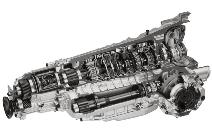
- 1.1 Illustration of transmission
- 1.2 Power flow diagram
- 1.3 Specifications
- 1.3.1 Screw specifications
- 1.3.1.1 Differential cover
- 1.3.1.2 Oil supply
- 1.3.1.3 Control unit
- 1.3.1.4 Oil pan
- 1.3.1.5 Cylinder F
- 1.3.1.6 Output
- 1.3.1.7 Yield limit tightening, differential crown wheel
- 1.3.1 Screw specifications
- 1.4 Adjusting work
- 1.4.0 Measuring the disc sets (procedure)
- 1.4.1 Clearances (snap ring)
- 1.4.1.1 Clearance, clutch F (snap ring)
- 1.4.1.2 Clearance, brake D (snap ring)
- 1.4.1.3 Clearance, clutch E (snap ring)
- 1.4.1.4 Clearance, clutch A (snap ring)
- 1.4.1.5 Clearance, clutch B (snap ring)
- 1.4.1.6 Clearance, brake C (snap ring)
- 1.4.2 Preload, differential
- 1.4.3 Bevel gear drive
- 1.4.3.1 Pinion position
- 1.4.3.2 Installed pinion shaft bearing height
- 1.4.3.3 Backlash / crown wheel position (only if no centring disc is installed)
- 1.4.3.4 Side shaft runout adjustment
- 1.4.4 Switch detent spring
- 1.4.5 Endplay, output (washer)
- 1.4.6 Output gear bearing adjustment
- 1.4.6.0 Preparation for bearing adjustment (shim washers)
- 1.4.6.1 Projection, front axle shaft bearing
- 1.4.6.2 Installation space, front axle shaft
- 1.4.6.3 Determining shim, front axle shaft
- 1.4.7 Play at input (washer)
- 1.5 Tightening torques
- 1.6 Checking transmission (on test rig/in vehicle)
- 1.7 Special tools
- 1.8 Oil flow diagram (position N according to DIN diagram)
- 1.9 Functional checks
- 1.9.1 Checking torsional clearance, Torsen II (angle) Removal
- 2.1 Removing converter, front axle output, control unit and position switch
- 2.1.1 Removing converter
- 2.1.2 Removing output to front axle
- 2.1.3 Dismantling work at the transmission housing
- 2.1.4 Removing control unit
- 2.1.5 Removing position switch
- 2.1.6 Removing shifting and parking lock mechanism
- 2.1.7 Removing oil pipes
- 2.2 Removing flange shaft and front axle differential
- 2.2.1 Removing flange shaft
- 2.2.2 Removing front axle differential
- 2.3 Removing pinion shaft
- 2.4 Removing oil supply
- 2.5 Removing input with tower
- 2.5.1 Removing input Dismantling
- 2.6 Dismantling Torsen II, cover, intermediate and transfer box housing
- 2.6.1 Torsen II
- 2.6.2 Intermediate housing
- 2.6.3 Cover
- 2.6.4 Distributor housing
- 2.7 Dismantling bearing shells, bearings etc.
- 2.7.1 Transmission housing
- 2.7.2 Front axle shaft
- 2.7.3 Rear axle shaft
- 2.7.4 Output gear
- 2.7.5 Differential cover
- 2.7.6 Pinion shaft
- 2.7.7 Differential (visual check)
- 2.7.8 Flange shaft
- 2.8 Oil supply
- 2.9 Brake F, towers I + II
- 2.9.1 Brake F (with 1st gear freewheel)
- 2.9.2 Brake D, E and clutch C
- 2.9.3 Planetary gear (III, II and I)
- 2.9.4 Tower II
- Installation
- Adjustments
- 3.1 Installing pinion shaft and differential
- 3.1.1 Differential
- 3.1.2 Pinion shaft
- 3.1.3 Installing pinion shaft
- 3.1.4 Pinion shaft torque check
- 3.1.5 Installing pinion shaft sealing ring and lateral shaft
- 3.1.6 Installing differential in transmission housing
- 3.2 Installing shift and parking lock mechanism
- 3.3 Brake F (with 1st gear freewheel)
- 3.4 Planetary gear (I, II and III)
- 3.4.1 Brakes (E and D)
- 3.4.2 Clutch C
- 3.5 Tower II (input with clutches A and B)
- 3.5.1 Clutch A (input)
- 3.5.2 Clutch B (input)
- 3.6 Oil supply
- 3.7 Adding parts to intermediate / transfer box housings, installing output
- 3.7.1 Torsen II
- 3.7.2 Adding various parts to the intermediate housing
- 3.7.3 Transfer box housing
- 3.7.3.1 Output gear
- 3.7.3.2 Rear axle shaft
- 3.7.3.3 Vibration damper
- 3.7.4 Front axle shaft
- 3.7.5 Intermediate housing
- 3.7.6 Installing intermediate gear and front axle shaft
- 3.7.7 Installing intermediate housing on transmission housing
- 3.7.8 Installing Torsen II
- 3.7.9 Installing transfer box housing at intermediate housing
- 3.8 Adding parts to flange shaft and installing
- 3.9 Installing control unit, oil filter and oil pan, position switch and converter
- 3.9.1 Installing control unit, oil filter and oil pan
- 3.9.2 Installing position switch and converter
- 3.9.2.1 Installing and checking position switch
- 3.9.2.2 Installing converter
- 3.9.3 Installing breather cover and protective transit caps
Language: English
Format: PDF
Pages: 200