
The Toyota RAV4 2000-2005 XA20 model is a reliable and popular compact SUV that requires proper maintenance to keep it running smoothly. If you’re experiencing any electrical issues with your vehicle, it’s important to have a reliable source of information to help you diagnose and repair the problem.
Our comprehensive guide to the Toyota RAV4 2000-2005 XA20 Fuse Box Diagram provides you with all the information you need to troubleshoot and repair any electrical issues with your vehicle. Our guide includes detailed diagrams of the fuse box system, covering every aspect from the power supply to the sensors and actuators.
We understand the importance of having user-friendly and easy-to-follow guides, which is why our guide is suitable for both professionals and DIYers. Our step-by-step instructions and tips will help you diagnose and fix any electrical problem with your Toyota RAV4 2000-2005 XA20 model quickly and efficiently.
With our guide, you’ll have access to detailed information on the fuse box system of your Toyota RAV4 2000-2005 XA20 model. You’ll be able to identify any issues with your vehicle’s electrical system and repair them with confidence.
In conclusion, our comprehensive guide to the Toyota RAV4 2000-2005 XA20 Fuse Box Diagram is the perfect solution for anyone experiencing electrical issues with their vehicle. Get your copy today and keep your Toyota RAV4 2000-2005 XA20 running smoothly.
Fuses and relays of Toyota Rav4 (LHD / RHD) with the engine: 1.8 l. – 1ZZ-FE, 2.0 L – 1AZ-FE, 2.0 l. – 1CD-FTV, 2.4 l. – 2AZ-FE (XA20; 2000, 2001, 2002, 2003, 2004, 2005)
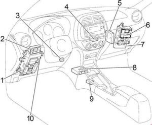
Cabin
LHD
RHD
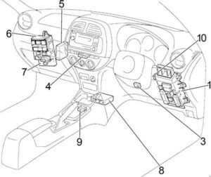
- Fuse box
- LHD: Daylight Relay
- Key transponder amplifier
- Air conditioner amplifier
- Engine and gearbox control unit (A / T)
- Engine control unit (M / T)
- Distribution block
- Distribution block
- Central airbag unit
- Gearbox selector lock control unit
- Direction indicator relay (alarm)
Cabin fuse box
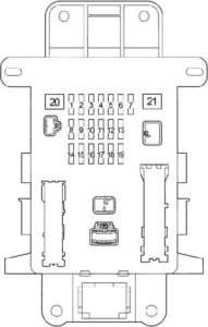
| No. | Name | A | Purpose |
| 1 | STOP | 10 | Brake light, brake light, ABS, gearbox selector lock, cruise control, multi – point fuel injection / sequential multi-point fuel injection |
| 2 | Cig | 15 | Cigarette lighter |
| 3 | POWER OUTLET | `5 | Power socket |
| 4 | S-HTR | 10 | Heated seats |
| 5 | Panel | 7.5 | Instrument panel lights, instrument cluster, front fog light, mirror heating, air conditioning |
| 6 | FR FOG | `5 | Front fog light |
| 7 | Horn | 10 | Sound signal |
| 8 | TAIL | 7.5 | Side light, license plate light, instrument panel illumination |
| 9 | TAIL & PANEL | 15 | Fuses “PANEL”, “TAIL” |
| 10 | ACC | 7.5 | Audio system, gear selector lock, clock, power mirrors |
| 11 | Def | 20 | Rear window defogger |
| 12 | GAUGE | 10 | Reverse lamps, cooling fan, air conditioning , automatic transmission indicators, charging system |
| 13 | OBD | 7.5 | Diagnostic connector |
| 14 | IG2 | 10 | Battery low indicator, multi-point fuel injection system / sequential multi-point fuel injection system, launch system, airbags, instrument cluster |
| 15 | Door | 20 | central locking |
| 16 | MIR HTR | 10 | Heated mirrors |
| 17 | RR WIP | 20 | Rear Wiper and Washer |
| 18 | WIP | 25 | Windshield Wiper and Washer |
| 18 | ECU IG | 10 | Alarms, instrument cluster, ABS, airbags, gear selector lock, cruise control, VSC, TRC |
| 20 | Power | 30 | Sunroof, power windows |
| 21 | AM1 | 40 | Sockets, rear window heating, fuses: “ACC”, “CIG”, “ECU IG”, “GAUGE”, “RR WIP”, “S − HTR” and “WIP” |
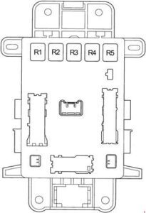
| No. | Relay |
| R1 | Sound signal |
| R2 | Rear Fog Light (RR FOG) |
| R3 | Rear Window Defogger (DEF) |
| R4 | Sockets (PWR OUTLET) |
| R5 | Power Windows, Sunroof (PWR) |
Engine compartment fuse box
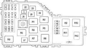
| No. | Name | A | Purpose |
| 1 | – | – | Jumper |
| 2 | ALT-S | 5 | Charging system |
| 3 | A / f | 20 | Air fuel ratio sensor |
| RADIO NO.2 | 13 | Audio system | |
| 4 | EFI1 | 20 | Multipoint fuel injection system / sequential multipoint fuel injection system, automatic transmission oil temperature sensor, fuses: “EFI2”, “EFI3” |
| 5 | Cut | 13 | Fuses: “RADIO”, “DOME” |
| 6 | Haz | 10 | Alarm |
| 7 | Efi2 | 5 | Multiport fuel injection system / sequential multiport fuel injection system |
| 8 | ABS 2 | `3 | ABS, VSC, TRC, brake assist system |
| 19 | DOME | 10 | Personal lighting, clock, interior lighting, air conditioning, wireless remote control system, high beam indicator, instrument cluster |
| 10 | MAIN | `3 | Fuses: “H − LP RH” and “H − LP LH” |
| 11 | EFI3 | 10 | Multiport fuel injection system / sequential multiport fuel injection system, toxicity reduction system |
| 12 | RADIO | 15 | Audio system |
| 13 | A / c | 5 | Air conditioning |
| 14 | IGN | 15 | Trigger System, multipoint fuel injection system / sequential multipoint fuel injection system |
| 15 | – | – | – |
| 16 | – | – | – |
| 17 | Ects | 10 | Electronic throttle control system |
| 18 | H − LP RH | 10 | Right headlight |
| 19 | H − LP LH | 10 | Left headlight |
| 20 | INJ | – | Multiport fuel injection system / sequential multiport fuel injection system |
| 21 | ST | 5 | Launch system |
| 22 | AM2 | 30 | Battery low indicator, multi-point fuel injection system / sequential multi-point fuel injection system, start-up system, airbags, fuse: “IG2” |
| 23 | Htr | 40 | Air conditioning / heater |
| 24 | H − LP CLN | 30 | Headlight Cleaners |
| F − htr | 30 | Fuel heating | |
| 25 | Cds | 30 | Cooling fan |
| 26 | ABS 1 | 40 | ABS |
| 50 | ABS | ||
| 27 | RDI | 30 | Cooling fan |
| Relay | |||
| R1 | Engine Control Module (EFI MAIN) | ||
| R2 | Cooling Fan (FAN NO.3) | ||
| R3 | Ignition (IG2) | ||
| R4 | Cooling Fan (FAN NO.2) | ||
| R5 | Air fuel ratio sensor (A / F) | ||
| R6 | Cooling Fan (FAN NO.2) | ||
| R7 | Fuel pump (C / OPN) | ||
| R8 | Heater (HTR) | ||
| R9 | Starter (ST) | ||
| R10 | Daytime Running Lights (DRL) | ||
| R11 | The engine control unit | ||
| R12 | – | ||