Toyota HiAce 2013 – 2018 Fuse Box Diagram
Fuses and relays Toyota HiAce (H200; 2013, 2014, 2015, 2016, 2017, 2018); Salon; LHD; RHD; Fuse box; Distribution block; Air conditioning amplifier; Gearbox control unit; Additional fuse box
Cabin
LHD
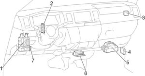
RHD
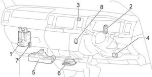
- Fuse box
- Distribution block
- Air conditioner amplifier
- Gearbox control unit
- Additional fuse box
- Airbag control unit
- Distribution Block (CAN)
- RHD: Transmission selector lock control unit
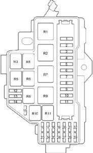
Cabin fuse box
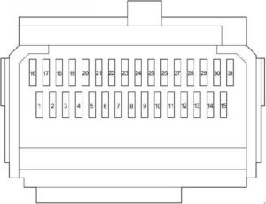
| No. | Name | And | Purpose |
| 1 | WIP FR | 25 | Front windshield wiper |
| 2 | R/B INPANE | 20 | |
| 3 | ACCL INT LCK | 25 | |
| 4 | WIP/WSH RR | 15 | Rear windshield wiper and washer |
| 5 | WSH FR | 10 | Front glass washer |
| 6 | ECU-IG NO. 1 | 7.5 | ABS, gearbox selector blocking |
| 7 | NO. | 10 | Charging system, watch, combination of appliances, cooling system fan, intelligent entry and launch system, front air conditioning, cabin lighting, electric sliding door, glass lifts, auxiliary heater (1KD-FTV, 2KD-FTV), rear window heating, seat belt indicator, wireless control system, distributed fuel injection system/system of sequentially fuel injection |
| 8 | OBD II | 7.5 | Diagnostic connector |
| 9 | STOP NO. 1 | 10 | Stop-signal lamps, ABS, cruise control, distributed fuel injection system/sequentially distributed fuel injection system, intelligent entry and launch system, gearbox selector lock |
| 10 | – | – | – |
| 11 | THE DOOR | 30 | Central lock, automatic lighting system, daytime running lights, intelligent entry and start system, front fog light, headlights, headlight corrector, lighting, cabin lighting, key buzzer, buzzer of light, electric drive sliding door, glass lifts, rear fog light, large light, wireless control system |
| 12 | HTR RR | 15 | Rear air conditioning |
| 13 | – | – | – |
| 14 | FR FOG | 10 | Front fog light |
| 15 | AM1 | 10 | Start-up system |
| 16 | TAIL | 10 | Dimensional light, front fog light, tail fog light, distributed fuel injection system/sequentially distributed fuel injection system |
| 17 | PANEL NO. 1 | 10 | Watch, combination of appliances, daytime running lights, illumination, key buzzer, buzzer of light, large light |
| 18 | A/C NO. 1 | 10 | Cooling system fan (5L-E), front air conditioner, auxiliary heater (1KD-FTV, 2KD-FTV), rear air conditioning |
| 19 | – | – | – |
| 20 | – | – | – |
| 21 | – | – | – |
| 22 | – | – | – |
| 23 | Cig | 15 | Cigarette lighter |
| 24 | ACC NO. 1 | 7.5 | Audio system, electric mirror drive |
| 25 | ACC NO. 2 | 7.5 | Gearbox selector lock |
| 26 | – | – | – |
| 27 | – | – | – |
| 28 | RR FOG | 10 | Rear fog light |
| 29 | WELCAB | 15 | – |
| 30 | A/B | 15 | Airbags, watches, combination of appliances |
| 31 | MET IGN | 10 | ABS, rear-speed lamps, charging system, clock, combination of appliances, daytime running lights, intelligent entry and start system, front air conditioning, headlights, automatic headlight corrector, lighting, cabin lighting, key buzzer, buzzer of light, electric sliding door, auxiliary heater (1KD-FTV, 2KD-FTV), airbag indicator, safety, light, speeding distributed fuel injection/sequentially distributed fuel injection system |
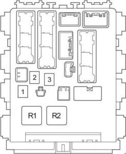
| No. | Name | And | Purpose |
| 1 | POWER | 30 | Glass lifters |
| 2 | – | – | – |
| 3 | Acc | 30 | Intelligent login and start-up system |
| Relay | |||
| R1 | Ignition (IG1) | ||
| R2 | The Heater (HTR) | ||
Additional fuse box in the passenger compartment
LHD
RHD
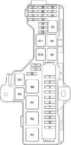
| No. | Name | A | Purpose |
| 1 | – | – | – |
| 2 | – | – | – |
| 3 | – | – | – |
| 4 | Drl | 10 | Daytime running lights |
| 5 | IGN NO.2 | 10 | Distributed Fuel Injection System/Consistent Distributed Fuel Injection System |
| 6 | IGN NO.1 | 15 | Distributed Fuel Injection System/Consistent Distributed Fuel Injection System |
| 7 | IG2-MAIN | 30 | Intelligent login and start-up system |
| 8 | H-LP RH-LO | 10 | LED: Middle right light, automatic lighting system, automatic headlight corrector |
| 9 | H-LP LH-LO | 10 | LED: Middle left light, automatic lighting system, automatic headlight corrector |
| 10 | H-LP RH-HI | 10 | LED: Far right light, automatic headlight corrector |
| 11 | H-LP LH-HI | 10 | LED: Far left light, automatic headlight corrector |
| 12 | Spare | – | Spare fuse |
| 13 | Spare | – | Spare fuse |
| 14 | Spare | – | Spare fuse |
| 15 | – | – | LHD: – |
| 16 | STOP NO.2 | 7.5 | Distributed Fuel Injection System/Consistent Distributed Fuel Injection System |
| 17 | A/C NO.2 | 7.5 | Front air conditioning |
| 18 | St | 7.5 | Launch system, distributed fuel injection system/sequentially distributed fuel injection system |
| 19 | H-LP LH-HI | 10 | Halogen Lamps: Far Left Light |
| 20 | H-LP RH-HI | 10 | Halogen Lamps: Far Right Light |
| 21 | H-LP LH-LO | 10 | Halogen lamps: Middle left light, headlight corrector |
| 22 | H-LP RH-LO | 10 | Halogen Lamps: Middle Right Light |
| 23 | ECU IG NO.2 | 7.5 | Internal mirror with automatic dimation, automatic lighting system, daytime running lights, central lock, intelligent system of entry and start, front fog light, headlights, headlight corrector, illumination, interior lighting key buzzer, buzzer light, parking assistance system, sliding door electric drive, rear fog light, large light, wireless control system |
| 24 | GAUGE NO.2 | 10 | ABS, internal mirror with automatic blackout, rear-speed lamps, gearbox indicators, parking assistance system, electric sliding door, seat belt indicator |
| 25 | – | – | – |
| 26 | – | – | – |
| 27 | – | – | – |
| 28 | – | – | – |
| 29 | – | – | – |
| Relay | |||
| R1 | Dimmer (headlight switch) | ||
| R2 | Headlights (HEAD) | ||
| R3 | – | ||
| R4 | Rear fog light (FOG RR) | ||
| R5 | – | ||
| R6 | Air conditioning compressor clutch (MG CLT) | ||
| R7 | Auxiliary heater (PTC NO.1) | ||
| R8 | – | ||
| R9 | Auxiliary heater (PTC NO.2) | ||
| R10 | Beep | ||
| R11 | Starter (ST) | ||
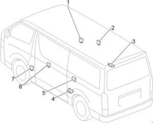
- Door control relay
- Door opening relay
- Sliding door electric relay
- Sliding door electric relay
- Central locking receiver
- Door opening relay
- Door control relay
Engine compartment
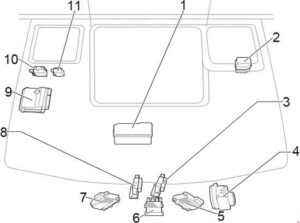
- Fuse box
- Additional fuse box
- 1TR-FE, 2TR-FE: Cooling fan control unit
- Brake control unit
- 1KD-FTV, 2KD-FTV, 5L-E: Cooling fan control unit
- 1KD-FTV (EURO5): Injector Control Unit
- 1KD-FTV, 2KD-FTV, 5L-E: Cooling fan control unit
- 1TR-FE, 2TR-FE: Cooling fan control unit
- The engine control unit
- 1TR-FE, 2TR-FE: Air Control Unit; 1KD-FTV (except EURO5), 2KD-FTV: Injector control unit
- Glow plug control unit
Engine compartment fuse box
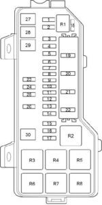
| No. | Name | A | Purpose |
| 1 | – | – | – |
| 2 | – | – | – |
| 3 | St | 40 | Intelligent login and start-up system |
| 4 | DOOR RR | 30 | Electric-driven luggage compartment door |
| 5 | A/PMP | 50 | 1TR-FE, 2TR-FE: Distributed Fuel Injection System/Consistent Distributed Fuel Injection System |
| 6 | ETCS | 10 | 1TR-FE, 2TR-FE: Throttle, distributed fuel injection system/sequentially distributed fuel injection system |
| 7 | EFI NO.2 | 10 | Distributed Fuel Injection System/Consistent Distributed Fuel Injection System |
| 8 | PSD RH | 25 | Electric drive sliding door |
| 9 | A/C NO.3 | 7.5 | Rear air conditioning |
| 10 | EFI NO.3 | 10 | 1TR-FE, 2TR-FE, 1KD-FTV: Distributed Fuel Injection System/Consistent Distributed Fuel Injection System |
| 11 | P/OUTLET | 15 | Outlet (lighter) |
| 12 | – | – | – |
| 13 | PTC NO.2 | 50 | Auxiliary heater |
| 14 | PTC NO.1 | 50 | Auxiliary heater |
| 15 | HTR FR | 40 | Front air conditioning, auxiliary heater |
| 16 | CLR RR | 30 | Rear air conditioning |
| 17 | Def | 50 | Heating the rear window |
| 18 | MIR HTR | 15 | Mirror heating |
| 19 | A/F HTR | 15 | Distributed Fuel Injection System/Consistent Distributed Fuel Injection System |
| 20 | EFI NO.1 | 25 | 1KD-FTV, 2KD-FTV, 5L-E: Distributed Fuel Injection System/Consistent Distributed Fuel Injection System |
| 21 | EFI NO.1 | 20 | 1TR-FE, 2TR-FE: Distributed Fuel Injection System/Consistent Distributed Fuel Injection System |
| Edu | 25 | 1KD-FTV, 2KD-FTV, 5L-E: Distributed Fuel Injection System/Consistent Distributed Fuel Injection System | |
| 22 | – | – | – |
| 23 | P/I NO.1 | 80 | Additional fuse block in the cabin |
| 24 | FAN NO.1 | 60 | Cooling system fan |
| 25 | Alt | 150 | Charging system, fuses: “J/B,” “DEF,” “HTR FR,” “CLR RR,” “PTC NO.1,” “PTC NO.2” |
| 26 | J/B | 100 | Block fuses in the cabin |
| 27 | FAN NO.2 | 60 | Cooling system fan |
| 28 | Glow | 80 | 1KD-FTV, 2KD-FTV, 5L-E: Engine pre-launch heating system |
| 29 | P/I NO.2 | 60 | Fuse: “A/F HTR,” “EFI NO.1,” “EDU” |
| 30 | – | – | – |
| Relay | |||
| R1 | Rear Air Conditioner (CLR RR) | ||
| R2 | Cooling system fan (FAN NO.1) | ||
| R3 | Cooling system fan (FAN NO.2) | ||
| R4 | Rear Glass Heating (DEF) | ||
| R5 | 1KD-FTV, 2KD-FTV, 5L-E: Incandescent Candles (GLOW) | ||
| R6 | 1KD-FTV, 2KD-FTV, 5L-E: – | ||
| R7 | 1KD-FTV, 2KD-FTV, 5L-E: – | ||
Additional fuse box in the engine compartment
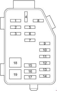
| No. | Name | A | Purpose |
| 1 | ABS SOL | 25 | Abs |
| 2 | HORN | 15 | Beep |
| 3 | ALT-S | 7.5 | Charging system |
| 4 | Def | 30 | Heating the rear window |
| 5 | RADIO | 15 | Audio system |
| 6 | DOME NO.2 | 10 | Salon lighting |
| 7 | DOME NO.1 | 10 | ABS, rear-speed lamps, watch, instrument combination, daytime running lights, distributed fuel injection system/sequentially distributed fuel injection system, intelligent entry and start system, front air conditioning, headlights (LED), automatic headlight corrector, lighting, cabin lighting, key buzzer, buzzer light, electric sliding door, auxiliary heater (1KD-FTV, 2KD-FTV), safety light turn pointers (emergency alarms), wireless control system |
| 8 | D/C CUT | 30 | Fuses: “RADIO’, “DOME NO.1,” “DOME NO.2” |
| 9 | AM2 | 7.5 | Electric trunk door drive, intelligent entry and start system, electric sliding door |
| 10 | TVSS | 15 | |
| 11 | TRN | 15 | Turning pointers (emergency alarm), clock, combination of devices |
| 12 | STRG LOCK | 10 | Intelligent login and start-up system |
| 13 | PSD LH | 25 | Electric drive sliding door |
| 14 | ECU-B | 10 | Immobiliser, intelligent entry and launch system, front air conditioning, electric sliding door, auxiliary heater (1KD-FTV, 2KD-FTV), wireless control system |
| 15 | HEAD | 40 | Headlights (halogen lamps), automatic lighting system, headlight corrector |
| 16 | DOOR R/L | 30 | Electric drive of the luggage compartment door, electric drive of the sliding door |
| 17 | DOOR BK | 30 | Electric drive of the luggage compartment door |
| 18 | ABS MTR | 40 | Abs |
| 19 | AM2 | 30 | Distributed Fuel Injection System/Consistent Distributed Fuel Injection System |