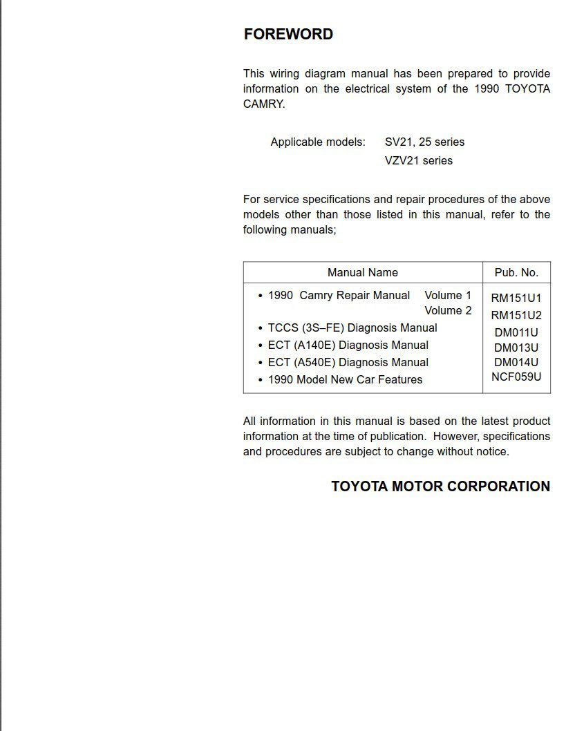
This wiring diagram manual has been prepared to provide information on the electrical system of the 1990 TOYOTA CAMRY. Applicable models: SV21, 25 series, VZV21 series. For service specifications and repair procedures of the above models other than those listed in this manual, refer to the following manuals
Manual Name Pub. No.
- 1990 Camry Repair Manual Volume 1 RM151U1
Volume 2 RM151U2 - TCCS (3S±FE) Diagnosis Manual DM011U
- ECT (A140E) Diagnosis Manual DM013U
- ECT (A540E) Diagnosis Manual DM014U
- 1990 Model New Car Features NCF059U
All information in this manual is based on the latest product information at the time of publication. However, specifications and procedures are subject to change without notice.
This manual provides information on the electrical circuits installed on vehicles by dividing them into each system circuit.
The actual wiring of each system circuit is shown from the point where the power source is received from the battery as far as each ground point. (All circuit diagrams are shown with the switches in the OFF position.)
When troubleshooting any problem, first understand the operation of the circuit where the problem was detected (see System Circuit section), the power source supplying power to that circuit (see Power Source section), and the ground points (see Ground Points section). See the System Outline to understand the circuit operation.
When the circuit operation is understood, begin troubleshooting of the problem circuit to isolate the cause. Use Relay Location and Electrical Wire Routing sections to find each part, junction block and wiring harness connectors, wiring harness and wiring harness connectors, and ground points of each system circuit. Internal wiring for each junction block is also provided for better understanding of connection within a junction block.
CONTENTS
- INDEX Index of the contents of this manual.
- INTRODUCTION Brief explanation of each section.
- HOW TO USE THIS MANUAL Instructions on how to use this manual.
- TROUBLE± SHOOTING Describes the basic inspection procedures for electrical circuits.
- ABBREVIATIONS Defines the abbreviations used in this manual.
- GLOSSARY OF TERMS AND SYMBOLS Defines the symbols and functions of major parts.
- RELAY LOCATIONS Shows position of the Electronic Control Unit, Computer, Relays, Junction Block, etc. This section is closely related to the system circuit.
- ELECTRICAL WIRE ROUTING Describes position of the Parts Connectors, Ground points, etc. This section is closely related to the system circuit.
- POWER SOURCE (POWER±LOAD, Reference) Describes power distribution from the power supply to various electrical loads.
- INDEX Index of the system circuits.
- SYSTEM CIRCUITS Electrical circuits of each system are shown from the power supply through ground points. Wiring connections and their positions are shown and classified by code according to the connection method. (Refer to the section, “How to use this manual”). The “System Outline” and “Service Hints” useful for troubleshooting are also contained in this section.
- GROUND POINTS Shows ground positions of all parts described in this manual.
- OVERALL WIRING DIAGRAM Provides circuit diagrams showing the circuit connections.
Language: English
Format: PDF
Pages: 185