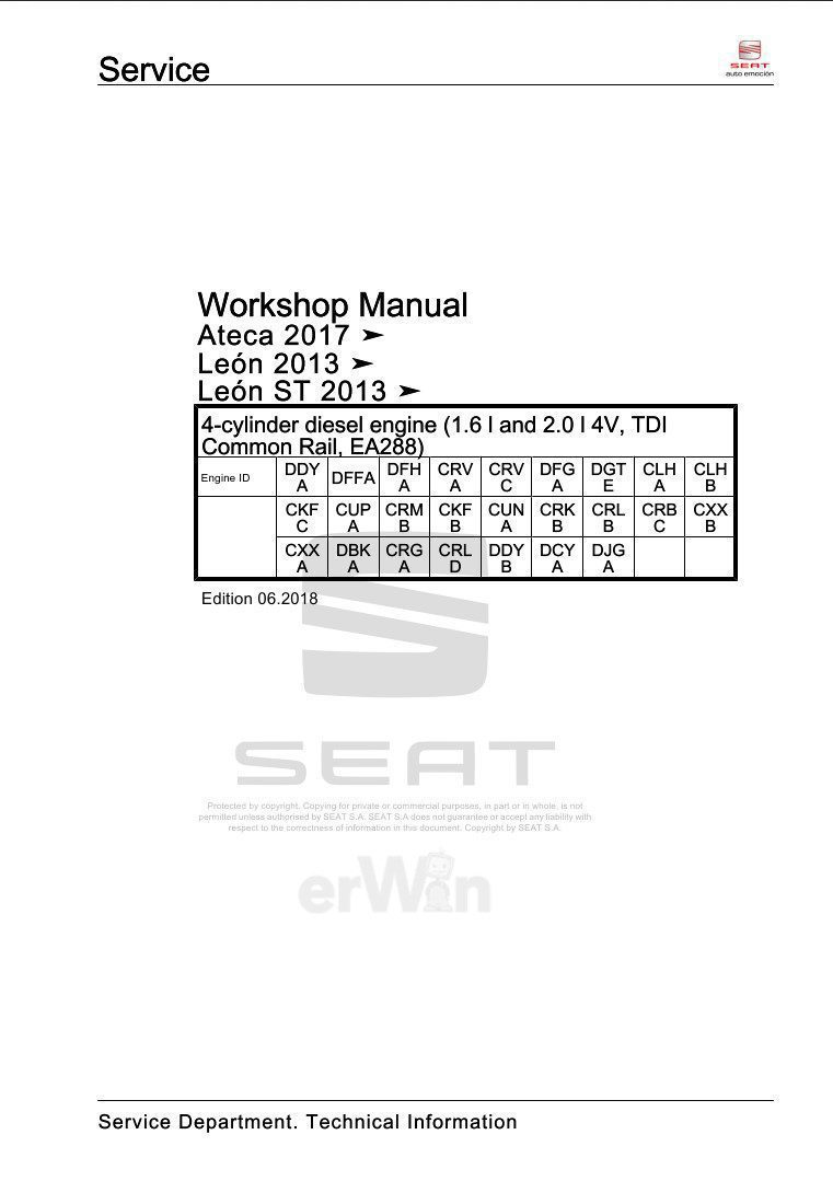
Ateca 2017- Leon 2013- Leon ST 2013- Workshop Manual. Edition 06.2018. Engine ID: DDYA, DFFA, DFHA, CRVA, CRVC, DFGA, DGTE, CLHA, CLHB, CKFC, CUPA, CRMB, CKFB, CUNA, CRKB, CRLB, CRBC, CXXB, CXXA, DBKA, CRGA, CRLD, DDYB, DCYA, DJGA. Technical information should always be available to the foremen and mechanics, because their careful and constant adherence to the instructions is essential to ensure vehicle road-worthiness and safety. In addition, the normal basic safety precautions for working on motor vehicles must, as a matter of course, be observed.
List of Workshop Manual Repair Groups
Repair Group
00 – Technical data
10 – Removing and installing engine
13 – Crankshaft group
15 – Cylinder head, valve gear
17 – Lubrication
19 – Cooling
21 – Turbocharging/supercharging
23 – Mixture preparation – injection
26 – Exhaust system
28 – Glow plug system
CONTENTS
- 00 – Technical data
- 1 Safety instructions
- 1.1 Safety precautions when working on fuel supply system
- 1.2 Safety precautions when working on vehicles with start/stop system
- 1.3 Safety precautions during road tests in which test and measuring equipment is used .
- 1.4 Safety precautions when working on the cooling system
- 1.5 Safety precautions when working on the SCR system
- 1.6 Safety precautions when working on exhaust system
- 2 Identification
- 2.1 Engine number, engine data
- 3 Repair instructions
- 3.1 Rules for cleanliness
- 3.2 Foreign objects in engine
- 3.3 Contact corrosion
- 3.4 Routing and attachment of lines
- 3.5 Installing radiators, coolers and condensers
- 4 Technical data
- 4.1 Coolant
- 1 Safety instructions
- 10 – Removing and installing engine
- 1 Removing and installing engine
- 1.1 Removing engine
- 1.2 Separating engine and gearbox .A.
- 1.3 Securing engine to engine
- 1.4 Installing engine
- 2 Assembly mountings
- 2.1 Assembly overview – assembly mountings
- 2.2 Removing and installing engine mountings
- 2.3 Removing and installing gearbox mounting
- 2.4 Removing and installing pendulum support
- 2.5 Supporting engine in installation position
- 2.6 Adjusting assembly mounting
- 2.7 Checking adjustment of assembly mountings (engine and gearbox mountings)
- 3 Engine cover
- 3.1 Removing and installing engine cover panel
- 1 Removing and installing engine
- 13 – Crankshaft group
- 1 Cylinder block (pulley end)
- 1.1 Assembly overview – cylinder block, pulley end
- 1.2 Assembly overview – sealing flange, pulley end
- 1.3 Removing and installing poly V-belt
- 1.4 Removing and installing tensioner for poly V-belt
- 1.5 Removing and installing vibration damper
- 1.6 Removing and installing ancillary bracket
- 1.7 Removing and installing engine support
- 1.8 Removing and installing sealing flange – pulley end
- 2 Cylinder block, gearbox end
- 2.1 Assembly overview – cylinder block, gearbox end
- 2.2 Removing and installing flywheel
- 2.3 Removing and installing sealing flange, gearbox side
- 3 Crankshaft
- 3.1 Assembly overview – crankshaft
- 3.2 Crankshaft dimensions
- 3.3 Renewing needle bearing in crankshaft
- 3.4 Measuring axial clearance of crankshaft
- 4 Pistons and conrods
- 4.1 Assembly overview – pistons and conrods
- 4.2 Removing and installing pistons
- 4.3 Measuring piston projection at TDC
- 4.4 Checking pistons and cylinder bores
- 4.5 Checking radial clearance of conrods
- 1 Cylinder block (pulley end)
- 15 – Cylinder head, valve gear
- 1 Cylinder head
- 1.1 Assembly overview – cylinder head
- 1.2 Assembly overview – cylinder head cover
- 1.3 Removing and installing cylinder head
- 1.4 Removing and installing cylinder head cover
- 1.5 Removing and installing seals for injectors
- 1.6 Removing and installing camshaft housing
- 1.7 Checking compression
- 2 loothed belt drive
- 2.1 Assembly overview – toothed belt cover
- 2.2 Assembly overview – toothed belt
- 2.3 Removing and installing toothed belt cover
- 2.4 Removing and installing toothed belt
- 2.5 Removing toothed belt from camshaft
- 3 Valve gear
- 3.1 Assembly overview – valve gear
- 3.2 Measuring axial play of camshaft
- 3.3 Removing and installing camshaft oil seal
- 3.4 Removing and installing camshaft adjuster
- 3.5 Removing and installing camshaft control valve 1 N205
- 3.6 Checking hydraulic compensation elements
- 3.7 Removing and installing valve stem seals
- 3.8 Removing and installing control valve for the camshaft adjuster
- 4 Inlet and exhaust valves
- 4.1 Checking valve guides
- 4.2 Checking valves
- 4.3 Valve dimensions
- 1 Cylinder head
- 17 – Lubrication
- 1 Sump, oil pump
- 1.1 Assembly overview – sump, oil pump
- 1.2 Engine oil
- 1.3 Removing and installing sump
- 1.4 Removing and installing lower part of sump
- 1.5 Removing and installing upper part of sump
- 1.6 Removing and installing oil pump
- 1.7 Removing and installing oil level and oil temperature sender G266
- 2 Engine oil cooler
- 3 Oil filter, oil pressure switch
- 3.1 Assembly overview – oil filter housing, oil pressure switch
- 3.2 Removing and installing oil pressure switch F1
- 3.3 Removing and installing oil pressure switch for reduced oil pressure F378
- 3.4 Checking oil pressure
- 3.5 Removing and installing oil filter housing
- 3.6 Removing and installing valve for oil pressure control N428
- 4 Oil circuit
- 4.1 Oil supply pipe: removing and fitting
- 4.2 Removing and installing oil return line for turbocharger
- 1 Sump, oil pump
- 19 – Cooling
- 1 Cooling system, coolant
- 1.1 Schematic diagram – coolant hoses
- 1.2 Checking cooling system for leaks
- 1.3 Draining coolant
- 1.4 Filling with coolant:
- 1.5 Checking electric vacuum pump VAS 6096/2
- 1.6 Flushing cooling system
- 1.7 Flushing cooling system, quick reference guide
- 2 Coolant pump, thermostat
- 2.1 Assembly overview – coolant pump, thermostat
- 2.2 Assembly overview – electric coolant pump
- 2.3 Assembly overview – coolant temperature sender
- 2.4 Removing and installing electric coolant pump
- 2.5 Removing and replacing coolant pump
- 2.6 Removing and installing thermostat
- 2.7 Testing coolant thermostat
- 2.8 Removing and installing the valve for the cylinder head coolant N489 . .
- 2.9 Removing and installing coolant temperature sender G62
- 2.10 Removing and installing radiator outlet coolant temperature sender G83
- 3 Coolant pipes
- 3.1 Assembly overview – coolant pipes
- 3.2 Removing and installing coolant pipes
- 4 Radiator, radiator fans
- 4.1 Assembly overview – radiator, radiator fan
- 4.2 Assembly overview – radiator cowl and radiator fans
- 4.3 Assembly overview – radiator blind
- 4.4 Removing and positioning radiator
- 4.5 Removing and installing cooler for charge air cooling circuit
- 4.6 Removing and installing radiator cowl
- 4.7 Removing and installing radiator fan
- 4.8 Removing and installing radiator blind
- 1 Cooling system, coolant
- 21 – Turbocharging/supercharging
- 1 Turbocharger
- 1.1 Assembly overview – turbocharger
- 1.2 Removing and installing turbocharger
- 1.3 Renewing vacuum unit for turbocharger
- 1.4 Removing and installing connection for turbocharger
- 2 Charge air system
- 2.1 Assembly overview – charge air system
- 2.2 Removing and installing charge pressure sender G31
- 2.3 Checking charge air system for leaks
- 2.4 Removing and installing air intake pipe
- 2.5 Checking charge air cooler for leaks
- 1 Turbocharger
- 23 – Mixture preparation – injection
- 1 Injection system
- 1.1 Schematic overview – fuel system
- 1.2 Fitting location overview – injection system
- 1.3 Filling and bleeding fuel system
- 1.4 Checking fuel system for leaks
- 2 Vacuum system
- 2.1 Schematic diagram – vacuum system
- 2.2 Removing and installing vacuum line
- 2.3 Checking vacuum system
- 3 Injectors and high-pressure accumulator (fuel rail)
- 3.1 Assembly overview – injectors
- 3.2 Assembly overview – high-pressure accumulator (fuel rail)
- 3.3 Adapting correction values for injectors
- 3.4 Testing injectors
- 3.5 Checking return flow rate of injectors with engine running
- 3.6 Checking return flow rate of injectors at starter speed
- 3.7 Testing jammed-open injectors
- 3.8 Removing and installing injectors
- 3.9 Removing and installing high-pressure pipes
- 3.10 Removing and installing fuel rail (rail)
- 4 Air filter
- 4.1 Assembly overview – air filter housing
- 4.2 Removing and installing air filter housing
- 5 Intake manifold
- 5.1 Assembly overview – intake manifold
- 5.2 Removing and installing intake manifold
- 5.3 Removing and installing throttle valve module J338
- 6 Senders and sensors
- 6.1 Removingrandd installing N276
- 6.2 Checking regulating valve N276
- 6.3 Removing and installing fuel pressure sender G247
- 6.4 Removing and installing air mass meter G70
- 6.5 Removing and installing pressure differential sender G505
- 6.6 Removing and installing exhaust pressure sensor 1 G450
- 6.7 Removing and installing NOx sender 2 G687
- 6.8 Removing and installing charge air temperature sender before charge air cooler G810
- 6.9 Removing and installing charge air temperature sender after charge air cooler G811
- 6.10 Removing and installing fuel temperature sender G81
- 6.11 Removing and installing control unit for NOx sender GX30
- 6.12 Removing and installing temperature and pressure sender for low-pressure fuel system GX20
- 7 Engine (motor) control unit
- 7.1 Removing and installing engine control unit J623
- 7.2 Removing and installing engine control unit J623 with protective housing
- 8 High-pressure pump
- 8.1 Assembly overview – high-pressure pump
- 8.2 Removing and installing high-pressure pump
- 9 Lambda probe
- 9.1 Assembly overview – Lambda probe
- 9.2 Removing and installing Lambda probe
- 1 Injection system
- 26 – Exhaust system
- 1 Exhaust pipes/silencers
- 1.1 Assembly overview – silencers
- 1.2 Assembly overview – front exhaust pipe
- 1.3 Removing and installing front exhaust pipe
- 1.4 Separating exhaust pipes, silencers
- 1.5 Removing and installing central exhaust pipe
- 1.6 Removing and installing rear silencer
- 1.7 Aligning exhaust system free of stress
- 1.8 Check exhaust system for leaks
- 1.9 Installation position of clamp
- 1.10 Aligning tailpipes
- 2 Emission control
- 2.1 Assembly overview – emission control
- 2.2 Removing and installing catalytic converter
- 2.3 Removing and installing particulate filter
- 2.4 Removing and installing emission control module
- 2.5 Removing and installing exhaust flap control unit J883
- 3 SCR system (selective catalytic reduction)
- 3.1 Assembly overview – reducing-agent tank
- 3.2 Assembly overview – delivery line for reducing agent
- 3.3 Assembly overview – delivery module for reducing agent
- 3.4 Removing and installing reducing agent tank
- 3.5 Removing and installing reducing agent supply line
- 3.6 Removing and installing delivery module for reducing agent
- 3.7 Removing and installing injector for reduction agent N474
- 3.8 Removing and installing control unit for reducing-agent heater J891
- 3.9 Assembly overview – injector for reducing agent N474
- 3.10 Drain the reducing agent tank
- 3.11 Removing and installing filler pipe for tank for reducing agent
- 3.12 Disconnecting reducing agent supply line
- 3.13 Resetting SCR learnt values
- 4 Exhaust gas temperature regulation
- 4.1 Assembly overview – exhaust gas temperature regulation
- 4.2 Removing and installing exhaust gas temperature sender 1 G235
- 4.3 Removing and installingi sender 2G448
- 4.4 Remove an co installingsexhaustigast temperaturesenderA3 G495
- 4.5 Removing and installing exhaust gas temperature sender 4 G648
- 5 Exhaust gas recirculation
- 5.1 Assembly overview – exhaust gas recirculation
- 5.2 Assembly overview – exhaust gas recirculation valve 1 GX5
- 5.3 Removing and installing exhaust gas recirculation cooler
- 5.4 Removing and installing exhaust gas recirculation valve 1 GX5
- 5.5 Removing and installing exhaust gas recirculation valve 2 GX6
- 5.6 Removing and installing exhaust gas recirculation temperature sensor G98 .
- 5.7 Checking exhaust gas recirculation cooler for leaks
- 1 Exhaust pipes/silencers
- 28 – Glow plug system
- 1 Glow plug system
- 1.1 Assembly overview – glow plug system
- 1.2 Removing and installing glow plug
- 1.3 Removing and installing automatic glow period control unit J179
- 1.4 Removing and installing Hall sender G40
- 1.5 Removing and installing engine speed sender G28
- 1 Glow plug system
Language: English
Format: PDF
Pages: 594
Seat 4-cylinder diesel engine 1.6L and 2.0L 4V, TDI Common Rail EA288