Type of Defect (FMI)
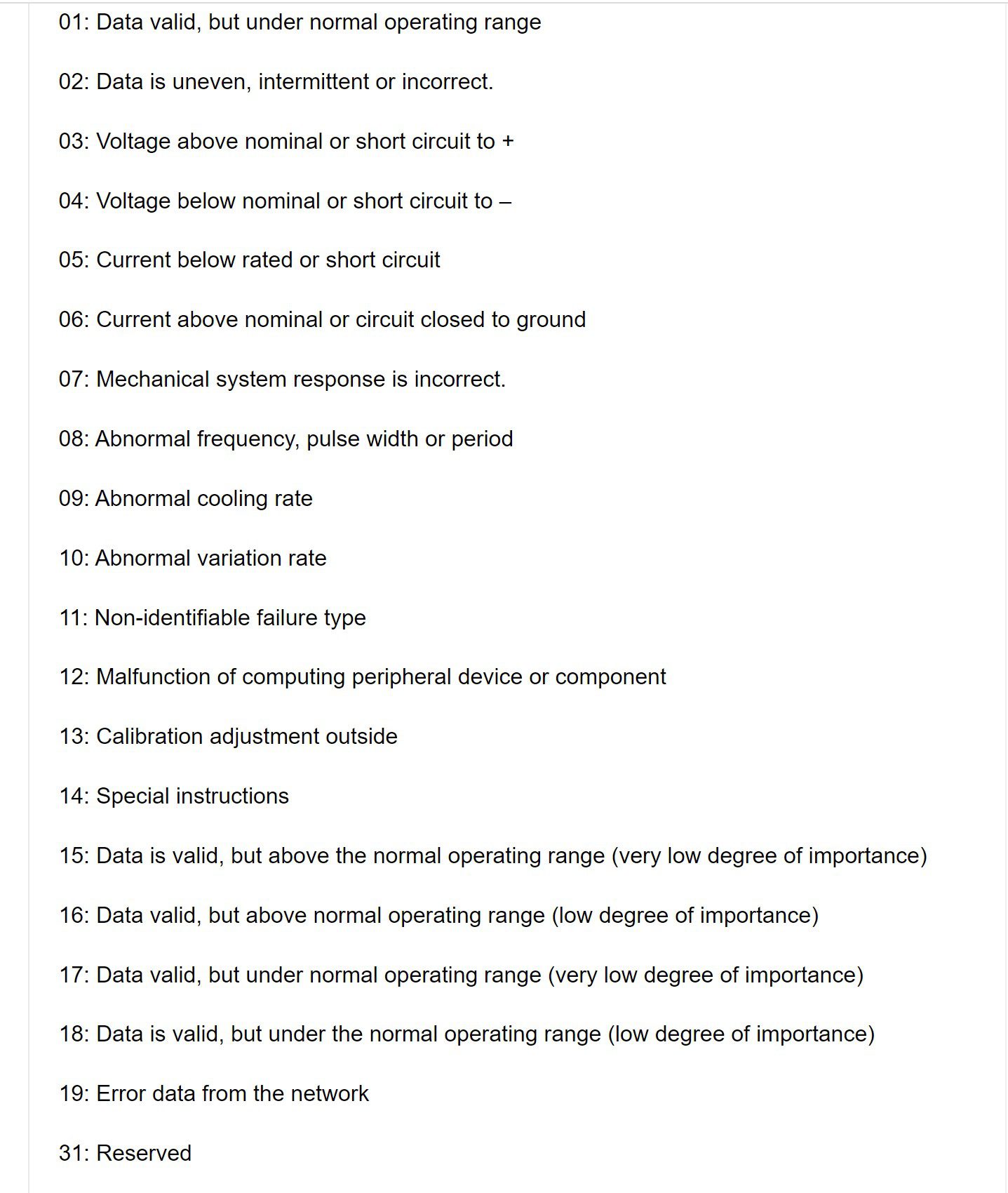
00: Data valid, but above normal operating range.
01: Data valid, but under normal operating range
02: Data is uneven, intermittent or incorrect.
03: Voltage above nominal or short circuit to +
04: Voltage below nominal or short circuit to –
05: Current below rated or short circuit
06: Current above nominal or circuit closed to ground
07: Mechanical system response is incorrect.
08: Abnormal frequency, pulse width or period
09: Abnormal cooling rate
10: Abnormal variation rate
11: Non-identifiable failure type
12: Malfunction of computing peripheral device or component
13: Calibration adjustment outside
14: Special instructions
15: Data is valid, but above the normal operating range (very low degree of importance)
16: Data valid, but above normal operating range (low degree of importance)
17: Data valid, but under normal operating range (very low degree of importance)
18: Data is valid, but under the normal operating range (low degree of importance)
19: Error data from the network
31: Reserved
Fault codes of truck control units, VECU
| Code | Malfunction | Repair method |
| SPN 91 FMI 3 | Accelerator pedal, power, short to positive. | Check the integrity and insulation of cable connections (SL2 / 3, SL2 / 4), check the supply voltage (4.5 – 5.25V). |
| SPN 91 FMI 3 | Accelerator pedal, signal, short to positive. | Check the integrity and insulation of cable connections with respect to +24 V. (SL2 / 4), operate the pedal and check the signal of the potentiometer (0.25 – 4.6 V). |
| SPN 91 FMI 3, 4 | Accelerator pedal, power, short to ground. | Check the integrity and insulation of cable connections (SL2 / 3, SL3 / 4), check the supply voltage (4.5 – 5.25V). |
| SPN 91 FMI 3, 4 | Accelerator pedal, signal, open circuit. | Check the integrity and insulation of the cable connections (SL2 / 3, SL2 / 5), operate the pedal and check the signal of the potentiometer (0.25 – 4.6 V). |
|
SPN 702 FMI 3 |
The output lock double H-shaped gearshift circuit, short to positive. | Check the integrity and insulation of cable connections with respect to +24 V. (SL2 / 9). |
| SPN 702 FMI 4 | The output of the lock is a double H-shaped gearshift circuit, an open circuit or short to ground. | Check the integrity and insulation of cable
compounds in relation to the mass. (SL2 / 9). |
| SPN 703 FMI 3 | Drive brake lights, open circuit or short to ground. | Check the integrity and insulation of cable connections with respect to +24 V. (SL2 / 10). |
| SPN 703 FMI 4 | Drive brake lights, short to ground. | Check the integrity and insulation of cable connections with respect to weight. (SL2 / 10). |
|
SPN 704 FMI 3 |
Stop signals on M, Austeras on H and P, switching off air conditioning on K, short to positive. | Check the integrity and insulation of cable connections with respect to +24 V. (SL2 / 13). |
| SPN 704 FMI 4 | Stop signals on M, Austeras on H and P, switching off air conditioning on K, open circuit or short to ground. | Check the integrity and insulation of cable connections with respect to weight. (SL2 / 13). |
|
SPN 705 FMI 4 |
Contact servo steering, open circuit. | Check the integrity of the connection (SL1 / 4). |
| SPN 729 FMI 11 | Air preheating, protection of the VECU unit is not operational. | Check the integrity and insulation of cable connections (SL2 / 9), check relays R15 and R16. |
|
SPN 730 FMI 11 |
Preheating is running continuously. There is a risk of fire. | Check the integrity and insulation of cable connections (SL2 / 9), check relays R15 and R16. |
| SPN 801 FMI 11 | Relay R18, contact or relay fault, open circuit on the contact or on the relay. | Verify the correct operation of the relay. |
| SPN 924 FMI 3 | M, N, K, weak speed output. R, exit Austeras. Short to positive | Check the integrity and insulation of cable connections with respect to +24 V. (SL2 / 8). |
| SPN 924 FMI 4 | M, N, K, weak speed output. R, exit Austeras. Open circuit or short to ground. |
Check the integrity and insulation of cable connections in relation to the mass (SL2 / 8). |
|
SPN 1194 FMI 13 |
Invalid parameterization. The VECU processor detects the presence of an anti-theft system when this function is not validated. | Restore the “anti-theft” function using a PC or remove the “anti-theft” transfer unit. |
| SPN 1195 FMI 8 | Anti-theft unit, lack of communication. | Check the integrity and insulation of cable connections (SL1 / 16, SL1 / 17). |
| SPN 1195 FMI 12 | Fault coding electronic lock. | Check that the key is recognized by the anti-theft system (the control indicator “anti-theft” lights up for 3 seconds when the contact is turned on and then goes out if the key is recognized). Check cable connections (SL1 / 16, SL1 / 17). |
| SPN 1195 FMI 12 | The problem in the software recognition of electronic lock. | Perform a full cycle of software recognition of electronic keys. |
|
SPN 1384 FMI 8 |
Sent messages are not acknowledged. | Ensure the correct functioning of the systems connected to the CAN data bus. Check CAN bus communications with all systems and check cable connections (SL3 / 3, SL3 / 4, SL3 / 6, SL3 / 7). |
| SPN 1384 FMI 8 | Open or short CAN line. | Check CAN bus communications with all systems and check cable connections (SL3 / 3, SL3 / 4, SL3 / 6, SL3 / 7). The resistance between the two wires must be 60 ohms. |
| SPN 1384 FMI 9 | The engine block does not respond to the CAN bus. | Check the diagnostic control of this system, check the CAN bus connections (SL3 / 3, SL3 / 4). The resistance between the two wires must be 60 ohms. |
| SPN 1624 FMI 18 | The speed sensor sends information believed to be incoherent by the VECU processor. | Check speed sensor connections. |
| SPN 1858 FMI 3 | Clock relay wiper, short to positive. | Check the integrity and insulation of cable connections with respect to +24 V. (SL2 / 11). |
|
SPN 1858 FMI 4 |
Clock relay wiper, open circuit circuit or circuit to mass of | Check the integrity and insulation of cable compounds by weight (SL2 / 11) |
| SPN 6000 FMI 14 | Requires programmed maintenance. | Perform maintenance. With INFOMAX, implement an update of operational control over maintenance operations. Activated exclusively on batch 2. |
|
SPN 170 FMI 3 |
Outside temperature sensor, open circuit or short to positive. | Check the integrity and insulation of cable connections with respect to +24 V. (SL1 / 1, SL1 / 2). |
| SPN 170 FMI 4 | Outside temperature sensor, short to ground. | Check the integrity and insulation of cable connections (SL1 / 1, SL1 / 2). |
| SPN 530 FMI 5 | Contact of the fuel filter, open circuit. | Check the contact and integrity of cable connections. |
|
SPN 551 FMI 11 |
Contamination of the fuel filter (check the contact and the integrity of the cable connections). | Replace fuel filters. |
|
SPN 558 FMI 7 |
The contact “accelerator pedal is raised” is blocked in the “closed” or “open” position. | Check the integrity of the connection on pins 3 and 4 of the pedal unit, when the pedal is raised, operate the pedal and check the switching state, check the cable connections (SL2 / 1) when switching the state. |
|
SPN 597 FMI 11,17 |
Brake pedal contact, contact misalignment. | Actuate the pedal and check the switching status on the contacts; when switching the status, check the cable connections (SL4 / 11). |
| SPN 598 FMI 7 | Contact clutch, contact stuck in a “closed” position. | Check contact, check cable connections (SL4 / 9). |
|
SPN 601 FMI 4 |
The malfunction on the handle “cruise control”, R / + and S / – simultaneously. | Check the cruise control knob of the cruise control and cable connections (SL4 / 7, SL4 / 8). |
|
SPN 604 FMI 7 |
The contact position of the neutral point is stuck in the “open” position. | Check contact and cable connections (SL4 / 5). |
|
SPN 604 FMI 7 |
The contact position of the neutral point is stuck in the “closed” position. | Check contact and cable connections (SL4 / 5). |
|
SPN 604 FMI 18 |
The speed sensor sends information, which is perceived by the VECU processor, as the lack of communication with the speed sensor. | Check speed sensor connections. |
|
SPN 608 FMI 8 |
CAN data bus, short to positive. Loss of communication with the indicator or anti-theft device. | Check cable connections (SL1 / 16, SL1 / 17). |
|
SPN 608 FMI 8 |
CAN data bus, malfunction. | Check cable connections (SL1 / 16, SL1 / 17). Disabled during parameterization. |
| SPN 608 FMI 9 | CAN data bus, malfunction, there is no connection with the indicator. | |
|
SPN 630 FMI 12 |
Erase or damage two saved zones. | Turn on the contact for a few seconds, turn off and wait for the power relay to open. Perform block parameterization. If the fault is stable, replace the VECU unit. |
|
SPN 630 FMI 12 |
The fault is inherent in the memory of DataMax dates. | Turn on the contact for a few seconds, turn off and wait for the power relay to open. If the fault is stable, replace the VECU unit. |
|
SPN 630 FMI 12 |
Flash malfunction, erase or damage two saved zones. | Perform block parameterization. If the fault persists, replace the unit VECU. |
| SPN 630 FMI 13 | Block parameterization or new block has not been performed. | Perform block parameterization. |
|
SPN 639 FMI 9 |
Astronic lever, CAN bus malfunction. | Ensure the correct operation of the CAN bus, check the integrity and isolation cable connections (SL3 / 3, SL3 / 4, SL3 / 6, SL3 / 7). |
|
SPN 639 FMI 9 |
EBS does not respond to the CAN data bus. | Perform system diagnostic monitoring, check CAN bus connections resistance between two wires must be 60 ohms. |
|
SPN 639 FMI 9 |
The retarder does not respond to the CAN data bus. | Perform system diagnostic monitoring, check CAN bus connections, resistance between two wires must be 60 ohms. |
|
SPN 639 FMI 9 |
Astronic, Allison or ZF Ecomat 2, does not respond to the CAN data bus. | Perform system diagnostic monitoring, check CAN bus connections, resistance between two wires must be 60 ohms. |
|
SPN 639 FMI 9 |
The tachograph is not responding via the CAN data bus. | Verify the correct functioning of the tachograph. Make sure it is correct connections between the tachograph and the unit VECU. |
| SPN 650 FMI 3 | Power relay, short to positive. | Check the integrity and insulation of cable compounds relative to +24 V. (SL3 / 9). |
|
SPN 650 FMI 4 |
Power relay, open circuit or short to ground. | Check the integrity and insulation of cable connections with respect to ground (SL3 / 9). Run this check after waiting at least 10 seconds after the contact is turned off. |
|
SPN 650 FMI 5 |
Power relay, open circuit. When the contact is turned on, the relay must be closed. | Check the integrity and insulation of cable connections (SL3 / 9). |
| SPN 650 FMI 7 | Power relay locked in “closed” position. | Ensure the correct operation of the relay. |
| SPN 650 FMI 7 | The power relay is locked in the “open” position. | Ensure the correct operation of the relay, check fuse. |
|
SPN 701 FMI 3 |
Drive, reversing lights, double H-shaped gearshift circuit, short to positive. |
Check the integrity and insulation of cable connections with respect to +24 V. (SL1 / 18). |
| SPN 701 FMI 4 | Drive, reversing lights, Double H-shaped gearshift circuit , open circuit or short to ground. | Check the integrity and insulation of cable connections with respect to weight. (SL1 / 18). |