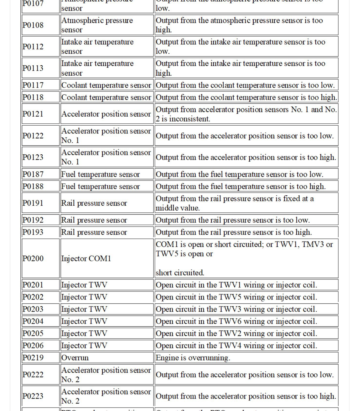
| DG Code | Source | Malfunction Outline |
| P0107 | Atmospheric pressure sensor | Output from the atmospheric pressure sensor is too low. |
| P0108 | Atmospheric pressure sensor | Output from the atmospheric pressure sensor is too high. |
| P0112 | Intake air temperature sensor | Output from the intake air temperature sensor is too low. |
| P0113 | Intake air temperature sensor | Output from the intake air temperature sensor is too high. |
| P0117 | Coolant temperature sensor | Output from the coolant temperature sensor is too low. |
| P0118 | Coolant temperature sensor | Output from the coolant temperature sensor is too high. |
| P0121 | Accelerator position sensor | Output from accelerator position sensors No. 1 and No. 2 is inconsistent. |
| P0122 | Accelerator position sensor No. 1 | Output from the accelerator position sensor is too low. |
| P0123 | Accelerator position sensor No. 1 | Output from the accelerator position sensor is too high. |
| P0187 | Fuel temperature sensor | Output from the fuel temperature sensor is too low. |
| P0188 | Fuel temperature sensor | Output from the fuel temperature sensor is too high. |
| P0191 | Rail pressure sensor | Output from the rail pressure sensor is fixed at a middle value. |
| P0192 | Rail pressure sensor | Output from the rail pressure sensor is too low. |
| P0193 | Rail pressure sensor | Output from the rail pressure sensor is too high. |
| P0200 | Injector COM1 | COM1 is open or short circuited; or TWV1, TMV3 or TWV5 is open or
short circuited. |
| P0201 | Injector TWV | Open circuit in the TWV1 wiring or injector coil. |
| P0202 | Injector TWV | Open circuit in the TWV5 wiring or injector coil. |
| P0203 | Injector TWV | Open circuit in the TWV3 wiring or injector coil. |
| P0204 | Injector TWV | Open circuit in the TWV6 wiring or injector coil. |
| P0205 | Injector TWV | Open circuit in the TWV2 wiring or injector coil. |
| P0206 | Injector TWV | Open circuit in the TWV4 wiring or injector coil. |
| P0219 | Overrun | Engine is overrunning. |
| P0222 | Accelerator position sensor No. 2 | Output from the accelerator position sensor is too low. |
| P0223 | Accelerator position sensor No. 2 | Output from the accelerator position sensor is too high. |
| P0227 | PTO accelerator position sensor | Output from the PTO accelerator position sensor is too low. |
| P0228 | PTO accelerator position sensor | Output from the PTO accelerator position sensor is too high. |
| P0234 | Abnormally boost pressure | Boost pressure is excessive or insufficient. |
| P0237 | Intake air pressure sensor | Output from the intake air pressure sensor is too low. |
| P0238 | Intake air pressure sensor | Output from the intake air pressure sensor is too high. |
| P0251 | Fuel leak | Fuel leak in the injection system or fuel system. |
| P0252 | Pressure limiter | Pressure limiter is operating. |
| P0253 | Abnormally high pressure 2 | Output from the rail pressure sensor is over the higher upper limit. |
| P0254 | Abnormally high pressure 1 | Output from the rail pressure sensor is over the lower upper limit. |
| P0255 | Supply pump | Rail pressure exceeds the specified duration or is over the specified
value. (Specified speed range.) |
| P0256 | Supply pump | Rail pressure exceeds the specified duration or is over the specified value (lower pressure and longer duration than PO255). (Medium to
high speed range.) |
| DG Code | Source | Malfunction Outline |
| P0257 | Supply pump | Poor pumping in the supply pump No. 1 cylinder. |
| P0335 | Engine speed sensor | No signal output from the engine speed sensor. |
| P0340 | TDC sensor | No signal output from the TDC sensor. |
| P0380 | Glow relay | BATT short in the output to the glow relay. Open or GND short in the
glow relay output. |
| P0500 | Vehicle speed sensor | Open or short circuit in the vehicle speed sensor; frequency is too
high; no output. |
| P0506 | IMC volume | IMC volume signal is too low. |
| P0507 | IMC volume | IMC volume signal is too high. |
| P0510 | IDLE switch | IDLE switch is seized closed. |
| P0600 | SLD system | Communication error between the vehicle speed control ECU and
engine ECU or vehicle speed sensor. |
| P0605 | CPU (in the engine ECU) | Main CPU malfunction or watchdog malfunction. |
| P0616 | Starter prohibition relay | BATT short in the output to the starter prohibition relay. |
| P0617 | Starter prohibition relay | Open circuit (external) or GND short in the output to the starter prohi-
bition relay. |
| P1121 | Intake throttle valve | Open circuit, GND short or BATT short in the output to valve MV1. |
| P1171 | Injection correction resistance value | Injection correction resistance value is too low. |
| P1172 | Injection correction resistance value | Injection correction resistance value is too high. |
| P1176 | Maximum speed adjusting resistor | Adjusting resistor value is too low. |
| P1177 | Maximum speed adjusting resistor | Adjusting resistor value is too high. |
| P1185 | Engine stop switch | Engine stop switch is seized closed. |
| P1200 | Injector COM2 | COM2 is open or short circuited; or TWV2, TWV4 or TWV6 is open or
short circuited. |
| P1210 | Capacitor charging circuit (ECU) | Malfunction in the injector drive power supply circuit (overcharging or
insufficient charging). |
| P1240 | Fuel system 1 | Large momentary fluctuations in No. 1 cylinder speed. |
| P1241 | Fuel system 5 | Large momentary fluctuations in No. 5 cylinder speed. |
| P1242 | Fuel system 3 | Large momentary fluctuations in No. 3 cylinder speed. |
| P1243 | Fuel system 6 | Large momentary fluctuations in No. 6 cylinder speed. |
| P1244 | Fuel system 2 | Large momentary fluctuations in No. 2 cylinder speed. |
| P1245 | Fuel system 4 | Large momentary fluctuations in No. 4 cylinder speed. |
| P1255 | Output to SCV | Open circuit (external) in ECU terminal SCV+ or SCV-, GND short, or
open circuit in SCV coil. |
| P1256 | Output to SCV | BATT short in ECU terminal SCV+ or SCV-. |
| P1257 | SCV | SCV seizure. |
| P1262 | Exhaust brake MV1 | Open circuit or GND short in the output to MV1. |
| P1263 | Exhaust brake MV1 | BATT short in the output to MV1. |
| P1605 | ECU | Malfunction in the flash memory. |
| P1930 | Power retarder relay | Open circuit, GND short or BATT short in the output to the retarder
relay. |
Mitsubishi Fuso Fighter ECU Related
External Wiring Diagram
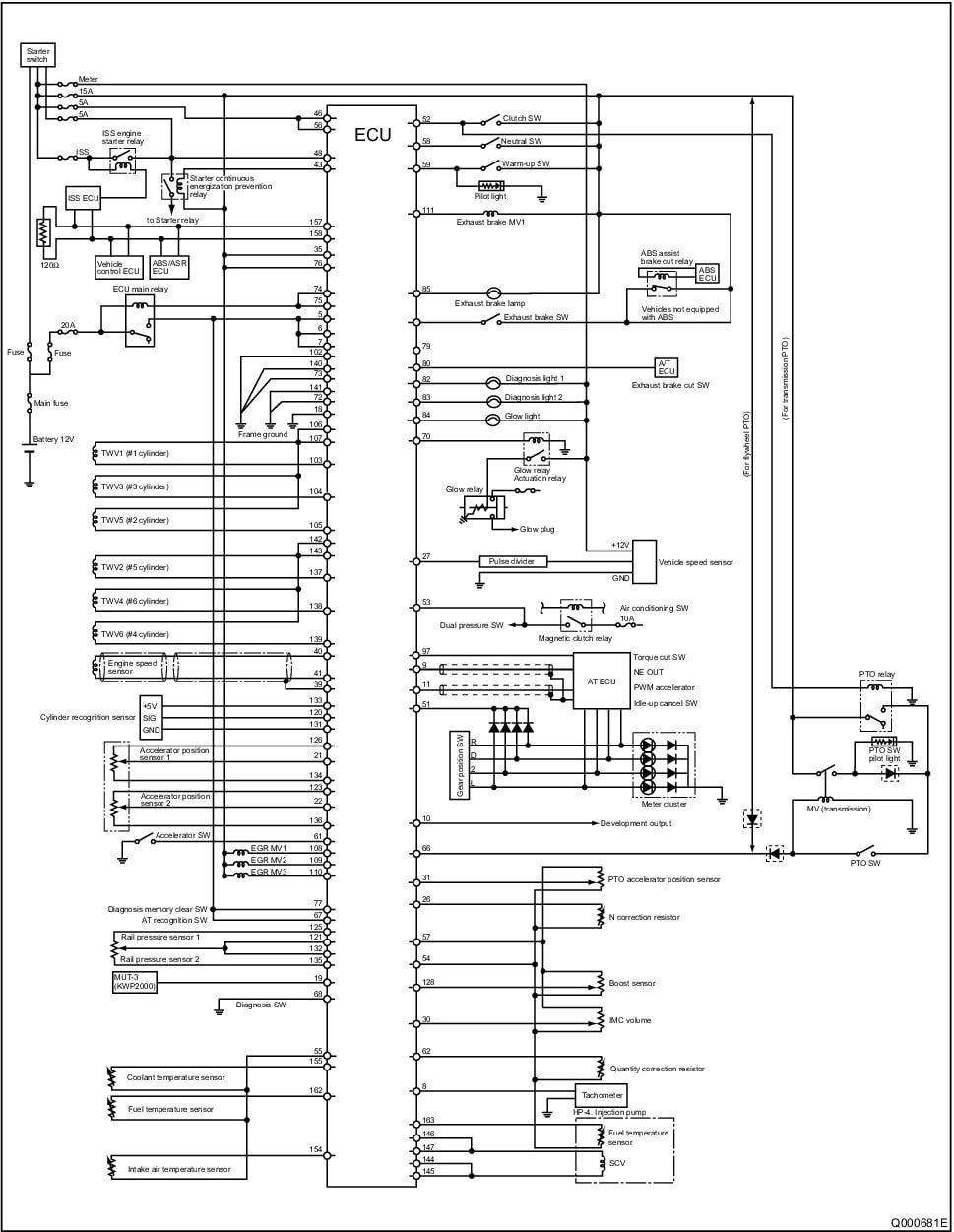
Mitsubishi Fuso Fighter ECU External Wiring Diagram
Terminal layout
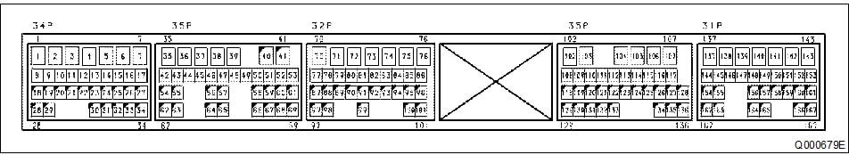
MITSUBISHI FUSO FIGHTER 6M60 Engine terminal layout
Terminal Symbol Explanation
Terminals No. 1 to 34
|
No. |
Terminal Name |
Signal Name |
No. |
Terminal Name |
Signal Name |
| 1 | – | – | 18 | CASEGND | Case ground |
| 2 | – | – | 19 | KWP2000 | MUT-3 |
| 3 | – | – | 20 | – | – |
| 4 | – | – | 21 | AD1 | Accelerator position sensor 1 |
| 5 | +B | +VB | 22 | AD2 | Accelerator position sensor 2 |
| 6 | +B | +VB | 23 | – | – |
| 7 | +B | +VB | 24 | – | – |
| 8 | TAC1 | Tachometer signal | 25 | AD19 | Temperature sensor 4 for after-treat-
ment (following EGR merging). |
| 9 | TAC2 | NE OUT | 26 | AD20 | N correction resistor |
| 10 | POUT1 | Development output (Q-OUT) | 27 | VS1 | Vehicle speed sensor |
| 11 | POUT2 | PWMACC | 28 | – | – |
| 12 | – | – | 29 | – | – |
| 13 | – | – | 30 | AD14 | IMC volume |
| 14 | – | – | 31 | AD15 | PTO accelerator position sensor |
| 15 | – | – | 32 | – | – |
| 16 | – | – | 33 | – | – |
| 17 | – | – | 34 | – | – |
Terminals No. 35 to 69
|
No. |
Terminal
Name |
Signal Name |
No. |
Terminal
Name |
Signal Name |
| 35 | +BF | SURGE OUT 1 | 53 | SW7 | Air conditioning switch |
| 36 | – | – | 54 | A-GND4 | Sensor GND4 |
| 37 | – | – | 55 | A-GND5 | Sensor GND5 |
| 38 | – | – | 56 | SW1 | Key switch |
| 39 | NE-SLD | NE-SLD | 57 | A-VCC4 | Sensor power supply 4 |
| 40 | NE+ | Engine speed sensor + | 58 | SW8 | Neutral switch |
| 41 | NE- | Engine speed sensor – | 59 | SW10 | Warm-up switch |
| 42 | – | – | 60 | – | – |
| 43 | OUT2 | Relay to prevent continuous starter
energization. |
61 | SW17 | Accelerator switch |
|
No. |
Terminal Name |
Signal Name |
No. |
Terminal Name |
Signal Name |
| 44 | – | – | 62 | AD21 | Quantity correction resistor |
| 45 | – | – | 63 | – | – |
| 46 | SW1 | Key switch | 64 | – | – |
| 47 | – | – | 65 | – | – |
| 48 | SW2 | Starter switch | 66 | SW9 | PTO switch |
| 49 | SW3 | Exhaust brake switch | 67 | SW11 | AT recognition switch |
| 50 | – | – | 68 | SW16 | Diagnosis switch |
| 51 | SW5 | Idle-up cancel switch | 69 | – | – |
| 52 | SW6 | Clutch switch 1 |
Terminals No. 70 to 101
|
No. |
Terminal
Name |
Signal Name |
No. |
Terminal
Name |
Signal Name |
| 70 | OUT19 | Glow relay actuation relay | 86 | – | – |
| 71 | – | – | 87 | – | – |
| 72 | GND | ECU analog GND | 88 | – | – |
| 73 | GND | ECU analog GND | 89 | – | – |
| 74 | OUT17 | ECU main relay | 90 | – | – |
| 75 | OUT18 | ECU main relay | 91 | – | – |
| 76 | +BF | SURGE OUT 2 | 92 | – | – |
| 77 | SW27 | Diagnosis memory clear switch | 93 | – | – |
| 78 | – | – | 94 | – | – |
| 79 | – | – | 95 | – | – |
| 80 | SW15 | Exhaust brake cut switch | 96 | – | – |
| 81 | – | – | 97 | – | – |
| 82 | S-OUT1 | Diagnosis light 1 (red) | 98 | – | – |
| 83 | S-OUT2 | Diagnosis light 2 (orange) | 99 | – | – |
| 84 | S-OUT3 | Glow light | 100 | – | – |
| 85 | S-OUT4 | Exhaust brake light | 101 | – | – |
Terminals No. 102 to 136
|
No. |
Terminal
Name |
Signal Name |
No. |
Terminal
Name |
Signal Name |
| 102 | P-GND | POWER GND | 120 | G | G sensor + |
| 103 | TWV1 | Injector drive signal 1 | 121 | AD4 | Rail pressure sensor 1 |
| 104 | TWV3 | Injector drive signal 3 | 122 | – | – |
| 105 | TWV5 | Injector drive signal 5 | 123 | A-VCC3 | Sensor power supply 3 |
| 106 | COMMON1 | Injector drive power supply 1-1 | 124 | – | – |
| 107 | COMMON1 | Injector drive power supply 1-2 | 125 | A-VCC2 | Sensor power supply 2 |
| 108 | – | – | 126 | A-VCC1 | Sensor power supply 1 |
| 109 | – | – | 127 | – | – |
|
No. |
Terminal Name |
Signal Name |
No. |
Terminal Name |
Signal Name |
| 110 | – | – | 128 | AD3 | Boost sensor |
| 111 | OUT12 | Exhaust brake MV1 | 129 | – | – |
| 112 | – | – | 130 | – | – |
| 113 | – | – | 131 | G-GND | G sensor |
| 114 | – | – | 132 | AD5 | Rail pressure sensor 2 |
| 115 | – | – | 133 | G-VCC | CAM ANGLE VCC (5V) |
| 116 | – | – | 134 | A-GND1 | Sensor GND1 |
| 117 | – | – | 135 | A-GND2 | Sensor GND2 |
| 118 | – | – | 136 | A-GND3 | Sensor GND3 |
| 119 | – | – |
Terminals No. 137 to 167
|
No. |
Terminal
Name |
Signal Name |
No. |
Terminal
Name |
Signal Name |
| 137 | TWV2 | Injector drive signal 2 | 153 | – | – |
| 138 | TWV4 | Injector drive signal 4 | 154 | AD6 | Intake air temperature sensor (before |
| 139 | TWV6 | Injector drive signal 6 | 155 | AD7 | Coolant temperature sensor |
| 140 | P-GND | POWER GND | 156 | – | – |
| 141 | P-GND | POWER GND | 157 | CAN1H | CAN1 HIGH |
| 142 | COMMON2 | Injector drive power supply 2-1 | 158 | CAN1L | CAN1 LOW |
| 143 | COMMON2 | Injector drive power supply 2-2 | 159 | – | – |
| 144 | SCVLO | HP3 and HP4 suction control valve
drive signal 1 |
160 | – | – |
| 145 | SCVLO | HP3 and HP4 suction control valve
drive signal 2 |
161 | – | – |
| 146 | SCVHI | HP3 and HP4 suction control valve
power supply 1 |
162 | AD8 | Fuel temperature sensor 1 (leak side) |
| 147 | SCVHI | HP3 and HP4 suction control valve
power supply 2 |
163 | AD9 | Fuel temperature sensor 2 |
| 148 | – | – | 164 | – | – |
| 149 | – | – | 165 | – | – |
| 150 | – | – | 166 | – | – |
| 151 | – | – | 167 | – | – |
| 152 | – | – |