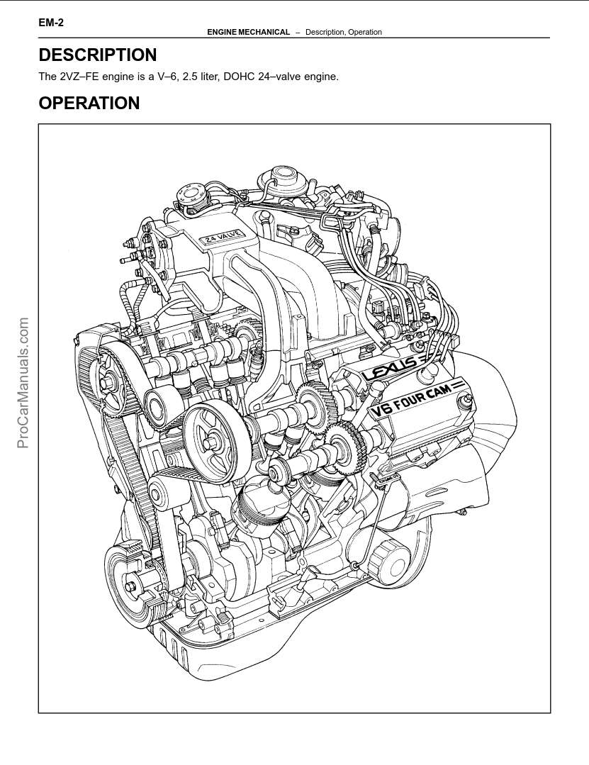
Lexus Engine 2VZ–FE Repair Manual PDF. The 2VZ–FE engine is a V–6, 2.5 liter, DOHC 24–valve engine. The 2VZ–FE engine has 6 cylinder in a V arrangement at a bank angle of 60°. From the front of the RH bank cylinders are numbered 1 – 3 – 5, and from the front of the LH bank cylinders are numbered 2 – 4 – 6. The crank-shaft is supported by 4 bearings inside the crankcase. These bearings are made of copper and lead alloy.
The crankshaft is integrated with 5 weights for balance. Oil holes are placed in the center of the crankshaft for supplying oil to the connecting rods, pistons and other components.
This engine’s ignition order is 1 – 2 – 3 – 4 – 5 – 6. The cylinder head is made of aluminum alloy, with a cross flow type intake and exhaust layout and with pent–roof type combustion chambers. The spark plugs are located in the center of the combustion chambers.
At the front and rear of the intake port of the intake manifold, a water passage has been provided which con-nects the RH and LH cylinder heads.
Exhaust and intake valves are equipped with irregular pitch springs made of special valve spring carbon steel which are capable of functioning no matter what the engine speed.
The RH and LH intake camshafts are driven by a single timing belt, and a gear on the intake camshaft en-gages with a gear on the exhaust camshaft to drive it. The camshaft journal is supported at 5 (intake) or 4 (ex-haust) places between the valve lifters of each cylinder and on the front end of the cylinder head. Lubrication of the cam journals and gears is accomplished by oil being supplied through the oiler port in the center of the camshaft.
Adjustment of the valve clearance is done by means of an outer shim type system, in which valve adjusting shims are located above the valve lifters. This permits replacement of the shims without removal of the cam-shafts.
The timing belt cover is composed of the resin type No.2 and No.1 above and below the engine RH mounting bracket.
Pistons are made of high temperature–resistant aluminum alloy, and a depression is built into the piston head to prevent interference with the valves.
Piston pins are the semi–floating type, with the pins fastened to the connecting rods by pressure fitting, allow-ing the pistons and pins to float.
The No.1 compression ring is made of steel and the No.2 compression ring is made of cast iron. The oil ring is made of a combination of steel and stainless steel. The outer diameter of each piston ring is slightly larger than the diameter of the piston and the flexibility of the rings allows them to hug the cylinder walls when they are mounted on the piston. Compression rings No.1 and No.2 work to prevent gas leakage from the cylinder and the oil ring works to clear oil off the cylinder walls to prevent it from entering the combustion chamber.
The cylinder block is made of cast iron with a bank angle of 60°. It has 6 cylinders which are approximately twice the length of the piston stroke. The top of the cylinders is closed off by the cylinder heads and the lower end of the cylinders becomes the crankcase, in which the crankshaft is installed. In addition, the cylinder block contains a water jacket, through which coolant is pumped to cool the cylinders.
The oil pan is bolted onto the bottom of the cylinder block. The oil pan is an oil reservoir made of pressed steel sheet. A dividing plate is included inside the oil pan to keep sufficient oil in the bottom of the oil pan even when the vehicle is tilted. This dividing plate also prevents the oil from making waves when the vehicle is stopped suddenly and thus shifting the oil away from the oil pump suction pipe.
CONTENTS
- ENGINE MECHANICAL
- Description, Operation
- Preparation
- Engine Tune–Up
- Engine Tune–Up, Idle and/or 2,500 rpm HC/CO Concentration Check Method
- Compression Check
- Timing Belt
- Cylinder Heads
- Cylinder Block
- Service Specifications
- EFI SYSTEM
- Preparation
- Operation (System Circuit)
- Description
- Precautions, Inspection Precautions
- Fuel System (Fuel Pump)
- Fuel System (Cold Start Injector)
- Fuel System (Fuel Pressure Regulator)
- Fuel System (Injectors)
- Fuel System (Fuel Tank and Lines)
- Air Induction System (Air Flow Meter)
- Air Induction System (Throttle Body)
- Air Induction System (Idle Speed Control (ISC) Valve)
- Electronic Control System (Location of Electronic Control Parts)
- Electronic Control System (EFI Main Relay)
- Electronic Control System (Circuit Opening Relay)
- Electronic Control System (Cold Start Injector Time Switch)
- Electronic Control System (Water Temperature Sensor)
- Electronic Control System (EGR Gas Temperature Sensor (CALIF. only))
- Electronic Control System (Fuel Pressure Control System)
- Electronic Control System (Oxygen Sensor (Main))
- Electronic Control System (Oxygen Sensor (Main), Sub–Oxygen Sensor (CALIF. only))
- Electronic Control System (Electronic Control Unit (ECU))
- Electronic Control System (Fuel Cut RPM)
- Service Specifications
- EXHAUST SYSTEM
- REPAIR INSTRUCTIONS
- EMISSION CONTROL SYSTEMS
- Component Layout and Schematic Drawing
- Positive Crankcase Ventilation (PCV) System
- Fuel Evaporative Emission Control (EVAP) System
- Exhaust Gas Recirculation (EGR) System
- Three–Way Catalyst (TWC) System
- COOLING SYSTEM
- Description, Operation
- Preparation
- Check and Replacement of Engine Coolant
- Water Pump
- Thermostat
- Radiator
- Electric Cooling Fans
- Service Specifications
- LUBRICATION SYSTEM
- Description, Operation
- Preparation
- Oil Pressure Check
- Replacement of Engine Oil and Oil Filter
- Oil Pump
- Service Specifications
- IGNITION SYSTEM
- Description
- Operation
- Preparation
- On-Vehicle Inspection
- Distributor
- Service Specifications
- ENGINE TROUBLESHOOTING
- Customer Problem Analysis Check Sheet
- Diagnosis System
- Symptom Simulation
- Terminals of ECU
- Diagnostic Code Chart
- Basic Inspection
- Matrix Chart of Problem Symptoms
- Circuit Inspection
Language: English
Format: PDF
Pages: 324