The GL1500 Service Manual includes all three 1994 models: Aspencade, SE, and Interstate. The GL1500 Service Manual and Electrical Troubleshooting Manual are combined in this single reference source. This manual features a seven-ring binder for easy use.
Most service procedures are based on the GL1500 Aspencade model. In those instances where service information for the SE and/or Interstate model differs, the text identifies the applicable model or models by the following codes: A (Aspencade), SE (SE), and I (Interstate).
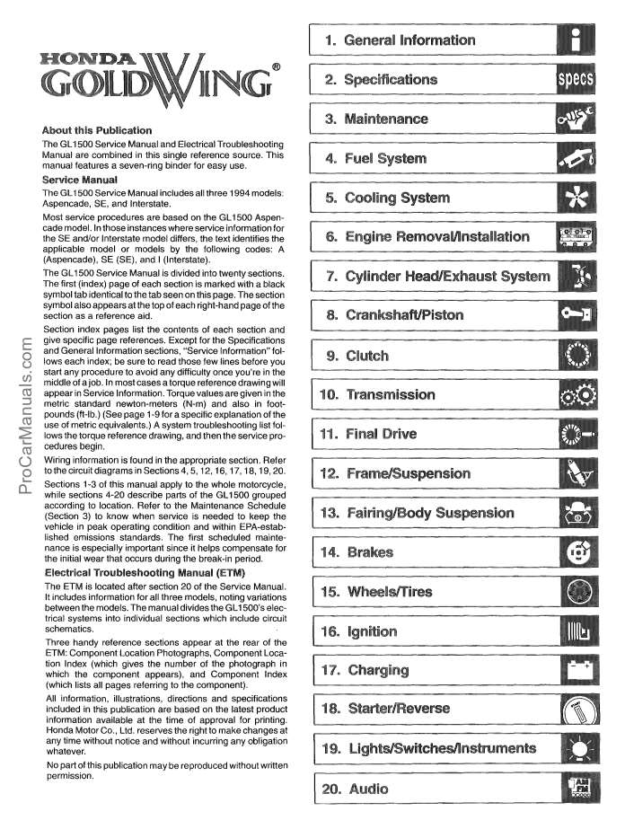
The GL1500 Service Manual is divided into twenty sections. The first (index) page of each section is marked with a black symbol tab identical to the tab seen on this page. The section symbol also appears at the top of each right-hand page of the section as a reference aid.
Section index pages list the contents of each section and give specific page references. Except for the Specifications and General Information sections, “Service Information” follows each index; be sure to read those few lines before you start any procedure to avoid any difficulty once you’re in the middle of a job. In most cases a torque reference drawing will appear in Service Information. Torque values are given in the metric standard newton-meters (N-m) and also in footpounds (ft-lb.) (See page 1 -9 for a specific explanation of the use of metric equivalents.) A system troubleshooting list follows the torque reference drawing, and then the service procedures begin.
Wiring information is found in the appropriate section. Refer to the circuit diagrams in Sections 4,5,12,16,17,18,19,20.
Sections 1-3 of this manual apply to the whole motorcycle, while sections 4-20 describe parts of the GL1500 grouped according to location. Refer to the Maintenance Schedule (Section 3) to know when service is needed to keep the vehicle in peak operating condition and within EPA-estab-lished emissions standards. The first scheduled maintenance is especially important since it helps compensate for the initial wear that occurs during the break-in period.
The ETM is located after section 20 of the Service Manual. It includes information for all three models, noting variations between the models. The manual divides the GL1500’s electrical systems into individual sections which include circuit schematics.
Three handy reference sections appear at the rear of the ETM: Component Location Photographs, Component Location Index (which gives the number of the photograph in which the component appears), and Component Index (which lists all pages referring to the component).
All information, illustrations, directions and specifications included in this publication are based on the latest product information available at the time of approval for printing. Honda Motor Co., Ltd. reserves the right to make changes at any time without notice and without incurring any obligation whatever.
CONTENTS
- 1. General Information
- 2. Specification
- 3. Maintenance
- 4. Fuel System
- 5. Cooling System
- 6. Engine Removal/Instalation
- 7. Cylinder Head/Exhaust System
- 8. Crankshaft/Piston
- 9. Clutch
- 10. Transmission
- 11. Final Drive
- 12. Frame/Suspension
- 13. Fairing/Body Suspension
- 14. Brakes
- 15. Wheels/Tires
- 16. Ignition
- 17. Charging
- 18. Starter/Reverse
- 19. Lights/Switches/lnstruments
- 20. Audio
Language: English
Format: PDF