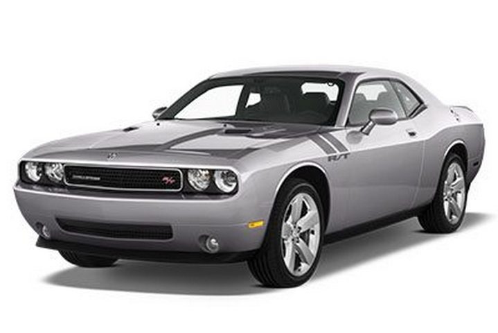
In this article we look at the third-generation Dodge Challenger before a facelift, produced from 2008 to 2014. Here you will find the 2009, 2010, 2011, 2012, 2013 and 2014 Dodge Challenger fuse box outline, information on the location of the fuse boxes inside the car and the allocation of each fuse (fuse layout).
The Dodge Challenger cigar lighter (outlet) fuses are #9 (power outlet) and #18 (instrument panel cigar lighter/selector outlet) located in the rear power distribution centre (trunk).
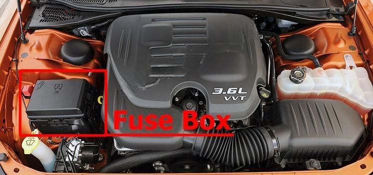
Fuse box location
Integrated Power Module
The Integrated Power Module (IPM) is located in the engine compartment, on the passenger side.
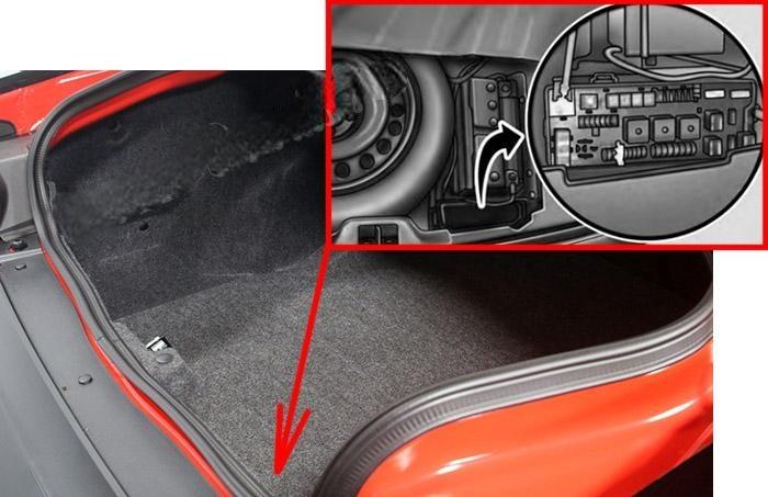
Rear Power Distribution Center
There is also a power distribution center located in the trunk under the spare tire access panel.
Fuse box diagrams
2009, 2010
Engine compartment
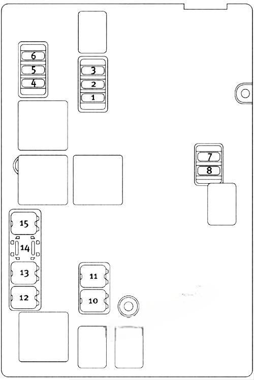
Fuse box diagram from the owner’s manual of 2010 is used. The location of fuses in cars produced at other times may differ
Assignment of fuses in the IPM (2009, 2010)
| Cavity | Cartridge Fuse | Mini-Fuse | Description |
|---|---|---|---|
| 1 | — | 15 Amp Blue | Washer Motor |
| 2 | — | 25 Amp Natural | Powertrain Control Module (PCM)/NGS Module Feed (Batt) |
| 3 | — | 25 Amp Natural | Ignition Run/Start |
| 4 | — | 25 Amp Natural | EGR Solenoid/Alternator |
| 5 | — | — | — |
| 6 | — | 25 Amp Natural | Ignition Coils/Injectors |
| 7 | — | — | — |
| 8 | — | 30 Amp Green | Starter |
| 9 | — | — | — |
| 10 | 30 Amp Pink | — | Windshield Wiper |
| 11 | 30 Amp Pink | — | Anti-Lock Brake System (ABS) Valves |
| 12 | 40 Amp Green | — | Radiator Fan Lo/High |
| 13 | 50 Amp Red | — | Anti-Lock Brake System (ABS) Pump Motor |
| 14 | — | — | — |
| 15 | 50 Amp Red | — | Radiator Fan |
| 16 | — | — | — |
| 17 | — | — | — |
| 18 | — | — | — |
| 19 | — | — | — |
| 20 | — | — | — |
| 21 | — | — | — |
| 22 | — | — | — |
Rear Power Distribution Center
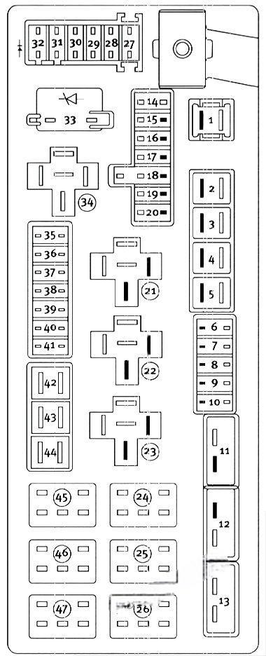
Fuse box diagram from the owner’s manual of 2010 is used. The location of fuses in cars produced at other times may differ
Assignment of fuses in the Rear Power Distribution Center (2009, 2010)
| Cavity | Cartridge Fuse | Mini-Fuse | Description |
|---|---|---|---|
| 1 | 60 Amp Yellow | Ignition Off Draw (IOD) Cavity 1 of the Rear Power Distribution Center contains a black IOD fuse needed for vehicle processing during assembly. The service replacement part is a 60 Amp yellow cartridge fuse. | |
| 2 | 40 Amp Green | — | Integrated Power Module (IPM) |
| 3 | — | — | — |
| 4 | 40 Amp Green | — | Integrated Power Module (IPM) |
| 5 | 30 Amp Pink | — | Heated Seats – If Equipped |
| 6 | — | 20 Amp Yellow | Fuel Pump |
| 7 | — | 15 Amp Blue | Audio Amplifier – If Equipped |
| 8 | 15 Amp Blue | Diagnostic Link Connector (DLC)/ Wireless Control Module (WCM)/Wireless Ignition Node (WIN) | |
| 9 | — | 20 Amp Yellow | Power Outlet |
| 10 | — | 25 Amp Natural | Vacuum Pump – If Equipped |
| 11 | 25 Amp circuit breaker | — | The cluster and the driver seat switch (Cavities 11, 12, and 13 contain self-resetting fuses (circuit breakers) that are only serviceable by an authorized dealer) |
| 12 | 25 Amp circuit breaker | — | The passenger seat switch (Cavities 11, 12, and 13 contain self-resetting fuses (circuit breakers) that are only serviceable by an authorized dealer) |
| 13 | 25 Amp circuit breaker | — | The door modules, the driver power window switch, and the passenger power window switch (Cavities 11, 12, and 13 contain self-resetting fuses (circuit breakers) that are only serviceable by an authorized dealer) |
| 14 | — | 10 Amp Red | AC Heater Control/Cluster/Security Module – If Equipped |
| 15 | — | 20 Amp Yellow | Active Damper – If Equipped |
| 16 | — | 20 Amp Yellow | Heated Seat Module – If Equipped |
| 17 | — | 20 Amp Yellow | Instrument Cluster |
| 18 | — | 20 Amp Yellow | Cigar Lighter (Instrument Panel) |
| 19 | — | 10 Amp Red | Stop Lights |
| 20 | — | — | — |
| 21 | — | — | — |
| 22 | — | — | — |
| 23 | — | — | — |
| 24 | — | — | — |
| 25 | — | — | — |
| 26 | — | — | — |
| 27 | — | 10 Amp Red | Occupant Restraint Controller (ORC) |
| 28 | — | 15 Amp Blue | Ignition Run, AC Heater Control/ Occupant Restraint Controller (ORC) |
| 29 | 5 Amp Tan | Cluster/Electronic Stability Control (ESC)/ Powertrain Control Module (PCM)/STOP LIGHT Switch | |
| 30 | — | 10 Amp Red | Door Modules/Power Mirrors/Steering Control Module (SCM) |
| 31 | — | — | — |
| 32 | — | — | — |
| 33 | — | — | — |
| 34 | — | — | — |
| 35 | — | 5 Amp Tan | Antenna Module – If Equipped/Power Mirrors |
| 36 | — | 25 Amp Natural | Hands-Free Phone – If Equipped/Radio/ Amplifier Feed |
| 37 | — | 15 Amp Blue | Transmission |
| 38 | — | 10 Amp Red | Cargo Light/Vehicle Information Module – If Equipped |
| 39 | — | 10 Amp Red | Heated Mirrors – If Equipped |
| 40 | — | 5 Amp Orange | Auto Inside Rearview Mirror/Heated Seats – If Equipped/Switch Bank |
| 41 | — | — | — |
| 42 | 30 Amp Pink | — | Front Blower Motor |
| 43 | 30 Amp Pink | — | Rear Window Defroster |
| 44 | 20 Amp Blue | — | Amplifier/Sunroof – If Equipped |
2011, 2013, 2014
Engine compartment
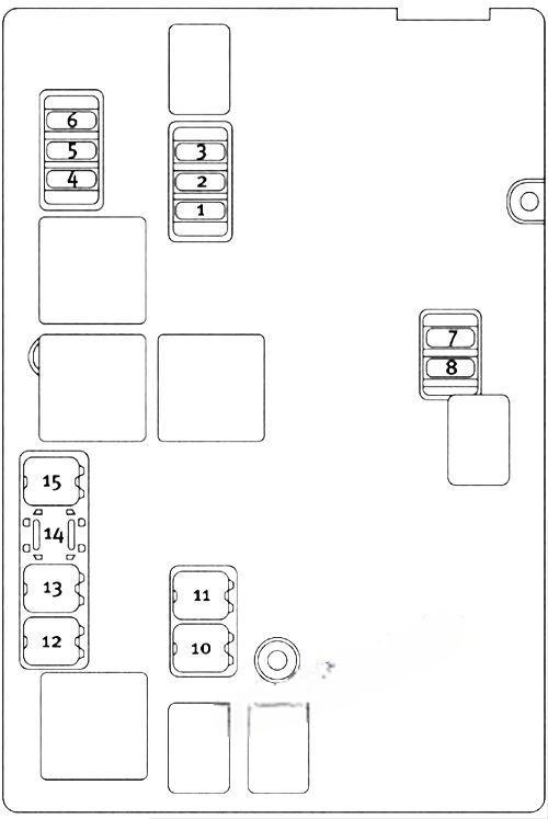
Fuse box diagram from the owner’s manual of 2010 is used. The location of fuses in cars produced at other times may differ
Assignment of fuses in the IPM (2011, 2013, 2014)
| Cavity | Cartridge Fuse | Mini-Fuse | Description |
|---|---|---|---|
| 1 | — | 15 Amp Blue | Washer Motor |
| 2 | — | 25 Amp Natural | Powertrain Control Module (PCM)/NGS Module Feed (Batt) |
| 3 | — | 25 Amp Natural | Ignition Run/Start |
| 4 | — | 25 Amp Natural | EGR Solenoid/Alternator |
| 5 | — | 15 Amp Blue | Powertrain Control Module |
| 6 | — | 25 Amp Natural | Ignition Coils/Injectors |
| 7 | — | 25 Amp Natural | Headlamp Washer Relay – If Equipped |
| 8 | — | 30 Amp Green | Starter |
| 9 | — | — | — |
| 10 | 30 Amp Pink | — | Windshield Wiper |
| 11 | 30 Amp Pink | — | Anti-Lock Brake System (ABS) Valves |
| 12 | 40 Amp Green | — | Radiator Fan Lo/High |
| 13 | 50 Amp Red | — | Anti-Lock Brake System (ABS) Pump Motor |
| 14 | — | — | — |
| 15 | 50 Amp Red | — | Radiator Fan |
| 16 | — | — | — |
| 17 | — | — | — |
| 18 | — | — | — |
| 19 | — | — | — |
| 20 | — | — | — |
| 21 | — | — | — |
| 22 | — | — | — |
Rear Power Distribution Center
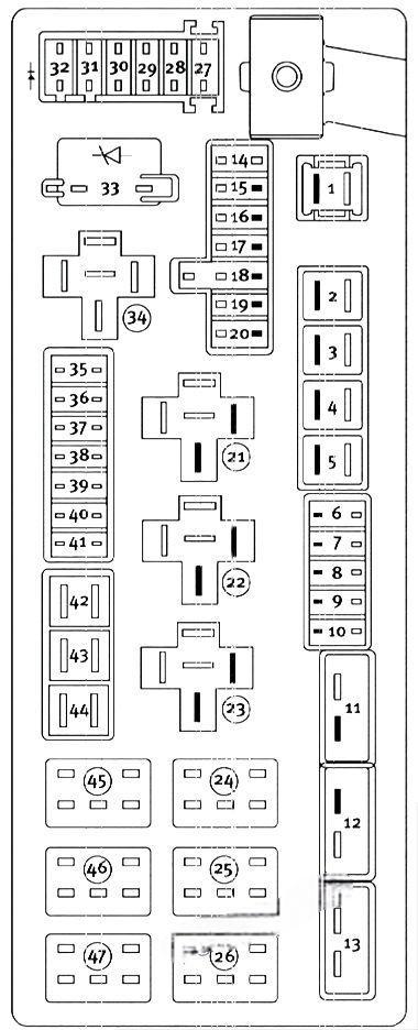
Fuse box diagram from the owner’s manual of 2010 is used. The location of fuses in cars produced at other times may differ
Assignment of fuses in the Rear Power Distribution Center (2011, 2013, 2014)
| Cavity | Cartridge Fuse | Mini-Fuse | Description |
|---|---|---|---|
| 1 | 60 Amp Yellow | Ignition Off Draw (IOD) Cavity 1 of the Rear Power Distribution Center contains a black IOD fuse needed for vehicle processing during assembly. The service replacement part is a 60 Amp yellow cartridge fuse. | |
| 2 | 40 Amp Green | — | Integrated Power Module (IPM) |
| 3 | — | — | — |
| 4 | 40 Amp Green | — | Integrated Power Module (IPM) |
| 5 | 30 Amp Pink | — | Heated Seats – If Equipped |
| 6 | — | 20 Amp Yellow | Fuel Pump |
| 7 | — | 15 Amp Blue | Audio Amplifier – If Equipped |
| 8 | 15 Amp Blue | Diagnostic Link Connector (DLC)/ Wireless Control Module (WCM)/Wireless Ignition Node (WIN) | |
| 9 | — | 20 Amp Yellow | Power Outlet |
| 10 | — | — | — |
| 11 | 25 Amp circuit breaker | — | The cluster and the driver seat switch (Cavities 11, 12, and 13 contain self-resetting fuses (circuit breakers) that are only serviceable by an authorized dealer) |
| 12 | 25 Amp circuit breaker | — | The passenger seat switch (Cavities 11, 12, and 13 contain self-resetting fuses (circuit breakers) that are only serviceable by an authorized dealer) |
| 13 | 25 Amp circuit breaker | — | The door modules, the driver power window switch, and the passenger power window switch (Cavities 11, 12, and 13 contain self-resetting fuses (circuit breakers) that are only serviceable by an authorized dealer) |
| 14 | — | 10 Amp Red | AC Heater Control/Cluster/Security Module – If Equipped |
| 15 | — | — | — |
| 16 | — | — | — |
| 17 | — | 20 Amp Yellow | Cluster |
| 18 | — | 20 Amp Yellow | Selectable Power Outlet |
| 19 | — | 10 Amp Red | Stop Lights |
| 20 | — | — | — |
| 21 | — | — | — |
| 22 | — | — | — |
| 23 | — | — | — |
| 24 | — | — | — |
| 25 | — | — | — |
| 26 | — | — | — |
| 27 | — | 10 Amp Red | Occupant Restraint Controller (ORC) |
| 28 | — | 10 Amp Red | Ignition Run |
| 29 | 5 Amp Tan | Cluster/Electronic Stability Control (ESC)/ Powertrain Control Module (PCM)/STOP LIGHT Switch | |
| 30 | — | 10 Amp Red | Door Modules/Power Mirrors/Steering Control Module (SCM) |
| 31 | — | — | — |
| 32 | — | — | — |
| 33 | — | — | — |
| 34 | — | — | — |
| 35 | — | 5 Amp Tan | Antenna Module – If Equipped/Power Mirrors |
| 36 | — | 25 Amp Natural | Hands-Free Phone – If Equipped/Radio/ Amplifier Feed |
| 37 | — | 15 Amp Blue | Transmission |
| 38 | — | 10 Amp Red | Cargo Light/Vehicle Information Module – If Equipped |
| 39 | — | 10 Amp Red | Heated Mirrors – If Equipped |
| 40 | — | 5 Amp Orange | Auto Inside Rearview Mirror/Heated Seats – If Equipped/Switch Bank |
| 41 | — | — | — |
| 42 | 30 Amp Pink | — | Front Blower Motor |
| 43 | 30 Amp Pink | — | Rear Window Defroster |
| 44 | 20 Amp Blue | — | Amplifier/Sunroof – If Equipped |