On this page, you can find a definition of fault codes for various Daewoo forklift models, including:
- G15S-2, G18S-2, G20SC-2 Plus, GC15S-2, GC18S-2, GC20SC-2 Plus
- GC20E-3, GC25E-3, GC30E-3, GC32E-3 Plus, G20E-3, G25E-3, G30E-3, G32E-3 Plus, GC20P-3, GC25P-3, GC30P-3, GC32P-3 Plus
- G20P-3, G25P-3, G30P-3, G32P-3, G33P-3 Plus, G35S-2, G40S-2, G45S-2, G50SC-2 Plus
- G50S-2, G60S-2, G70S-2 Plus
These codes apply to Daewoo forklifts with serial number prefixes: FQ, FR, FY, G2, G3, G4, G5, G6, G9, GA, GB, GH, GQ. The trucks with the “Plus” designation near the model number indicate this on the side.
Diagnostics:
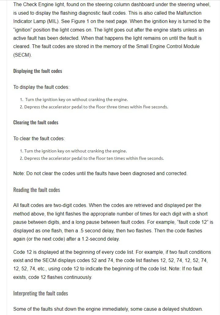
The Check Engine light, also known as the Malfunction Indicator Lamp (MIL), is located on the steering column dashboard under the steering wheel. This light displays flashing diagnostic fault codes. When the ignition key is turned to the “ignition” position, the light comes on. It goes out after the engine starts unless an active fault is detected. In such cases, the light remains on until the fault is cleared. The fault codes are stored in the memory of the Small Engine Control Module (SECM).
Displaying the fault codes:
To display the fault codes:
- Turn the ignition key on without cranking the engine.
- Depress the accelerator pedal to the floor three times within five seconds.
Clearing the fault codes:
To clear the fault codes:
- Turn the ignition key on without cranking the engine.
- Depress the accelerator pedal to the floor ten times within five seconds.
Note: Do not clear the codes until the faults have been diagnosed and corrected.
Reading the fault codes:
All fault codes consist of two digits. When retrieved and displayed as described above, the light flashes the appropriate number of times for each digit, with a short pause between digits and a long pause between fault codes. For example, “fault code 12” is displayed as one flash, a 0.5-second delay, and then two flashes. The code then repeats (or the next code) after a 1.2-second delay.
Code 12 is displayed at the beginning of every code list. For example, if there are two fault conditions and the SECM displays codes 52 and 74, the code list flashes 12, 52, 74, 12, 52, 74, 12, 52, 74, etc., using code 12 to indicate the start of the code list. Note: If no fault exists, code 12 will flash continuously.
Interpreting the fault codes:
Some faults cause the engine to shut down immediately, while others result in a delayed shutdown. Some trigger a “limp home” mode, while others simply indicate a fault without further action taken by the SECM.
The following page provides a list of all the fault codes with brief descriptions, serving as a fault-code “cheat sheet” for LP engines. It is essential for Daewoo technicians to have a copy of this list on hand, especially with the introduction of new low-emission trucks. Daewoo recommends that technicians practice displaying fault codes on new trucks, and code 12 can be displayed when no fault condition exists.
Manuals:
Woodward Industrial Controls has published manuals for each of the three types of engines equipped with their fuel systems on Daewoo trucks. These manuals contain detailed descriptions of the fault codes and troubleshooting procedures. You can find the manuals on our website in PDF format, titled “Fuel System Supplement” in the Service Literature section. Please download these files to your computer as needed. As new versions of engine service manuals from Daewoo become available, they will also be posted on the website and made available through our Parts Department. Please check the website periodically for updates specific to your model and serial number.
Support:
The combination of the fault-code cheat sheet and the manuals from the Daewoo website should provide technicians with a solid starting point for troubleshooting in case of a fault condition. Please utilize these available resources before contacting Daewoo product support.
Daewoo Tier II engine/fuel system fault codes
| FAULT CODE | NAME | FAULT DESCRIPTION |
| 12 | NONE | Signifies the end of one pass through the fault list |
| 14 | ECTSensorInputLow | Normally set if the coolant sensor wire is shorted to ground |
| 15 | ECTSensorInputHigh | Set if the coolant sensor wire is disconnected or open |
| 16 | ECTRangeHigh | Coolant sensor has measured an excessive temperature or shorted to GND |
| 22 | ThrottleSensorInputLo | TPS1 signal wire is open |
| 23 | ThrottleSensorInputHi | TPS1 signal wire is shorted |
| 24 | ThrottleSensorRangeLo | TPS Sensor malfunction |
| 25 | ThrottleSensorRangeHi | TPS Sensor malfunction |
| 26 | ETCSticking | ETC driver signal wire is open or the throttle plate is sticking inside the throttle body |
| 27 | PredictedTPSDifference | TPS1 is different than calculated position |
| 28 | ETCSpringTestFailed | Throttle return spring failed keyup test |
| 29 | ETCDriverFault | Throttle driver over-current or driver signals shorted |
| 33 | MapSensorInputLow | MAP signal disconnected or open circuit |
| 34 | MapSensorInputHigh | MAP signal shorted or sensor failure |
| 37 | IATSensorInputLow | TMAP sensor failure or shorted circuit |
| 38 | IATSensorInputHigh | TMAP disconnected or IAT signal open |
| 42 | EST1Low | Coil driver signal low or under current |
| 43 | EST1High | Coil driver signal high or over current |
| 52 | LowOilPressure | Low engine oil pressure |
| 53 | BatterySensorInputLow | Battery voltage measured below 8.0 VDC |
| 54 | BatterySensorInputHigh | Battery voltage measured above 15.9 VDC |
| 55 | XDRPSensorInputLow | Measured sensor transducer power is below 4.6 VDC |
| 56 | XDRPSensorInputHigh | Measured sensor transducer power is above 5.2 VDC |
| 57 | Engine OverSpeed | RPM increased above maximum rpm setpoint |
| 61 | Pedal1SensorInputLo | APP1 signal disconnected, open circuit or sensor malfunction |
| 62 | Pedal1SensorInputHi | APP1 sensor failure or shorted circuit |
| 63 | Pedal1SensorRangeLo | APP1 potentiometer malfunction |
| 64 | Pedal1SensorRangeHi | APP1 potentiometer malfunction |
| 65 | Pedal2SensorInputLo | APP2 sensor failure or shorted signal |
| 66 | Pedal2SensorInputHi | APP2 signal disconnected, open circuit or sensor malfunction |
| 67 | Pedal2SensorRangeLo | APP2 potentiometer malfunction |
| 68 | Pedal2SensorRangeHi | APP2 potentiometer malfunction |
| 69 | Pedal1ToPedal2Difference | Measured APP2 pedal position signal is different than APP1 signal |
| 71 | AFRTrimValveOutput | FTV modulation driver signal fault |
| 72 | AFRTrimValveLowerDC | FTV duty cycle at lower (LEAN) limit |
| 73 | AFRTrimValveUpperDC | FTV duty cycle at upper (RICH) limit |
| 74 | O2SensorSwitching | O2 sensor not switching across the reference AFR voltage |
| 77 | OxygenSensorInputHigh | O2 sensor signal shorted to +5 VDC |