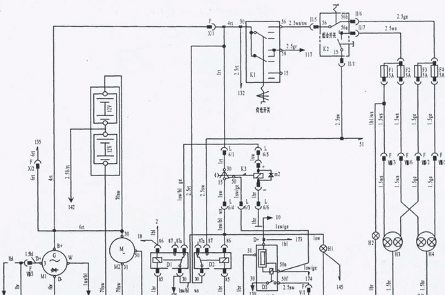
M1 is a 3-phase alternator.
M2 is a starter.
N1, N- rechargeable battery.
D1 – the ignition switch D of the steering wheel + relay.
D2 – the ignition switch 15 of the steering wheel, relay.
D3 – protective relay starter.
K1 – the main light switch.
K2 – combined switch.
K3 – starter switch and ignition switch on the steering wheel.
H1 – charge indicator.
H2 is a driving light indicator.
H3 – left head light.
H4 – right head light.
F1 – left headlight for main beam fuse 5A and indicator.
F2 – fuse 5A of the right headlight for the driving beam.
F3 – fuse 5A of the left front dipped beam headlamp.
F4 – the fuse for the right front dipped beam headlamp.
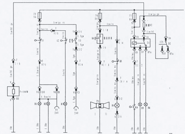
R1-stove.
R2 – lowering the resistance of the revolutions of high and low speeds of the stove.
K1 – stop switch.
K2- reverse switch.
K4- the button of the signal of the combined switch.
K5 – neutral switch.
K6-switch low and high speed.
H1-left stop lamp.
H2 is the right stop lamp.
H3- reverse lamp.
Н4 – the indicator of the neutralizer switch.
H5 is an indicator of low speed.
H6 – high speed indicator.
D1 – relay switching low and high speed.
D2 – relay switching low and high speed.
F5 – a fuse A5 of a brake lamp and a backing.
F6 – signal and neutral indicator of the fuse 5A
F7-fuse 8A high and low speed and stove.
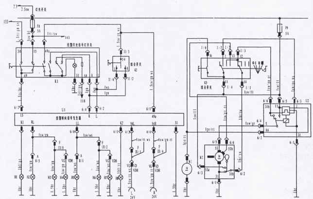
U1 – integral turn signal relay.
U2 – integral pulse signal relay wiper blade.
M1 is the electric motor of the washer pump.
M2 – the wiper motor.
К1 – switch of the blinking control signal.
K2- on the combined switch, turn switch to the left, to the right.
К3- on the combined switch, the switch of management of a screen wiper.
F8-fuse 8A of the control system of a flashing light bulb.
F9-fuse 5A brush control system.
H1 – indicator of the tractor’s turning signal.
H2 – right side turn lamp.
H3 – right front turn lamp.
H4 – right rear turn lamp.
Н5- left side lamp.
H6 – left front turn lamp.
H7 – left rear turn lamp.
Н8 – the indicator of a turn signal of the trailer.
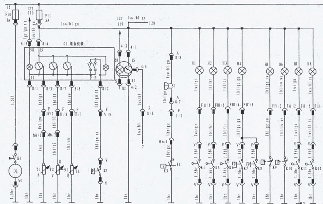
M1-generator
G1- combined device.
G2 – tachometer.
S1 – sound signal.
T1 – sound signal.
T2 is the oil pressure sensor.
T2 – water temperature sensor
T3 – fuel quantity sensor
H1-indicator of front differential lock
H2 – the differential lock indicator of the first rear axle.
Н3 – the indicator of blocking of differential of the second back bridge.
H4 indicator of the dispensing box
Н5 – the indicator of management of a body-tipper.
Н6 – the indicator of a manual brake.
Н7 – the indicator of forward longitudinal blocking of differential.
Н8 – the indicator of forward longitudinal blocking of differential.
К2- the switch of the third brake return.
К3- water temperature control switch.
K4 – the switch of blocking of differential.
K5 – the switch of blocking of differential of the first bridge.
K6 – the switch of blocking of differential of the second bridge.
K7 – power steering control switch Ι
К8- power steering control switch Ι Ι
К9 – the switch of management of a body-dumper.
K10 – manual brake control switch.
K11- front longitudinal differential lock
К12 – the switch of blocking of back longitudinal differential
F11 – fuse 5A of all control switches and devices
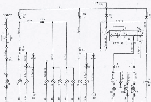
K1-switch of the rear working lamp (autom. Category S)
K2-switch lighting control devices.
D1- light inversion relay.
H1 – rear working lamp (auto category S)
H2 – left side parking lamp
H3 – left rear lamp.
H4 indicator
H5- left lamp of overall height.
H6- right lamp of overall height.
H7 – left lamp overall.
H8 – right lamp overall.
H9 – right side parking lamp.
H10- right rear lamp.
H11- rear fog lamp.
Н12- left fog lamp.
H13- right fog lamp.
F13 – fuse 5A left night traffic.
F14 is the right side lamp 5A fuse.
F15- fog lamp fuse 5A and instrument lighting regulator.
F16-fuse 5A light inversion relay.
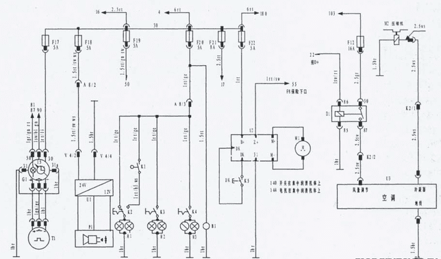
G1 – the cadometer.
T1- speedometer sensor.
U1 – voltage converter 24 \ 12 volts
P1- radio tape recorder
M1 – central lubrication motor
M2-air compressor (optional)
D1-conditioner relay (optional)
К2-switch of cabin illumination
K3- lamp switch for reading
K4- lamp switch for reading
K5 – centralized lubrication control switch.
В1- external power supply socket (24V)
Н1 – a lamp of illumination of a cabin
H2-reading lamp
H3-reading lamp
F17-fuse 5A power source of the speedometer
F18- power supply fuse 5A
F19 – fuse 5A power supply converter
F20 – cab light fuse 5A
F21 – fuse 8A relay start interlock
F22 – fuse 5A of the centralized lubrication power supply
F12-fuse 16A of the power source of the air conditioner.
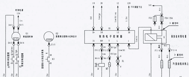
G1-clock and tachometer
G2-kilometers on the speedometer and the total score
K1- Clock setting button
K2- minute setting button
K3- inversion of kilometers of speedometer (small account and amount)
U1 – electric preheating sensor
D- solenoid valve for fuel supply during start-up
DL-indicator of preheating
RT-sensor for preheating control
P- resistance of left heating candle
P- resistance of right heating candle
K- preheating start relay
F24 – fuse 25A preheating start