Astra HD8Ec Fault Codes list (Blink Codes)
Diagnosis
Electrical faults and certain mechanical faults detected by the electronic control unit can be diagnosed by means of the Blink Code and diagnostic instruments.
Blink Code
The EDC is designed to provide information on engine faults. The warning light comes on while the engine is running, to indicate a fault has occurred, which could be:
| Warning light on | Serious fault
Degraded system function |
| Warning light blinking | Very serious fault
Degraded system function Loss of one or more safety functions and possible engine stop |
Information on the type of fault is given in the form of a code by the EDC warning light consisting of a series of long or short blinks (the blink code).
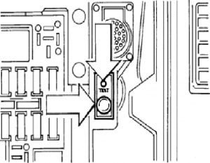
To check the fault, use the diagnosis button located under the UCI compartment hatch, which has another EDC warning light operating in parallel with the one on the dashboard.
Dashboard warnings lights
Fault checking/identification procedure
- Stop vehicle and switch off engine (STOP);
- Turn key to RUN (warning lights on and engine off);
- Press diagnosis button and check that the EDC warning light blinks once;
- After a short interval during which the warning light remains off, it begins to blink initially at long intervals and then shorter.

EDC Diagnosis Button
The fault code is explained in the following pages.
For example: code 1.4 means that the warning light has given one long blink and four short ones. The procedure should be repeated until the code of the first indicated fault is repeated again.
- Fault memory cancellation procedure from drivers seat
- Press the Blink Code button (with key to stop);
- Turn key to RUN holding down the button;
- Wait 5 seconds;
- Turn key to stop;
- Check cancellation by reading number by means of test button.
EDC electronic control unit blink code table
| Blink Code | EDC warning light * | Fault |
| VEHICLE AREA | ||
| 1.1 | ON | Vehicle speed sensor |
| 1.2 | ON | Torque selector |
| 1.3 | OFF | Cruise control |
| 1.4 | ON | Accelerator pedal |
| 1.5 | OFF | Clutch pressure switch |
| 1.6 | ON | Brake pedal switch signal plausibility |
| 1.7 | OFF | Plausibility between brake / accelerator pedal |
| ENGINE AREA | ||
| 2.1 | OFF | Water temperature sensor |
| 2.2 | OFF | Air temperature sensor |
| 2.3 | OFF | Fuel temperature sensor |
| 2.4 | ON | Turbo pressure sensor |
| 2.5 | OFF | (Control unit) ambient temperature sensor |
| 2.6 | ON | Engine braking switch signal |
| 3.5 | OFF | Battery voltage |
| TURBO AREA | ||
| 4.1 | OFF | Turbo actuator pressure sensor |
| 4.2 | ON | Turbine revs sensor |
| 4.3 | ON | Turbine overspeed |
| 4.4 | ON | Turbo management (mechanical fault) |
| 4.5 | ON | VGT solenoid valve |
| 4.6 | BLINKING | Engine braking solenoid valve |
| INJECTORS | ||
| 5.1 | ON | Cylinder 1 injector fault |
| 5.4 | ON | Cylinder 4 injector fault |
| 5.2 | ON | Cylinder 2 injector fault |
| 5.6 | ON | Cylinder 6 injector fault |
| 5.3 | ON | Cylinder 3 injector fault |
| 5.5 | ON | Cylinder 5 injector fault |
| ENGINE REVS SENSOR | ||
| 6.1 | ON | Flywheel sensor |
| 6.2 | ON | Valve train sensor |
| 6.4 | OFF | Engine overspeed |
| INTERFACE WITH OTHER CONTROL UNITS | ||
| 7.1 | OFF | P.W.M. ABS/ASR interface |
| 7.2 | OFF | CAN line |
| 7.3 | OFF | CAN line (ASR management) |
| 7.4 | OFF | CAN line (gearbox data management) |
| ENGINE CONTROL UNIT | ||
| 9.1 | BLINKING | Faulty control unit |
| 9.2 | ON | EEPROM data incorrect |
| 9.3 | BLINKING | Immobilizer |
| 9.4 | ON | Main relay |
| 9.5 | ON | Engine stop procedure error |
| 9.6 | ON | Control unit data recording error |
|
* Blink code warning light off – Slight fault Blink code warning light on – Serious fault Blink code warning light blinking – Very serious fault |
||